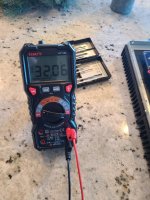
Nm i read the instructions wrong on this.I figured out the negative voltage, and luckily I hadn't returned one of the power supplies yet. One of my boards measured great. The other everything is OK except for I'm only getting 4 lights and measuring from TP104 to speaker ground I'm getting - 32.36v which is less than than 0.080 stated, but is it OK to be that much less? What should I look for if that's not ok? I knocked c123 and c124 around a little when trying to install transistors, could that be it?
Trying to adjust the dc offset. R25 measurements move when i measure it on pins 1 and 2. When measuring on TP104 and tp100 I get no movement at all, stays at - 32v. D10 and D11 don't light up either, but are fed enough power to light up.
TP106 to - rail measures 0.15v lower than the positive rail of 0.75v, not sure if that part matters or not.
Any suggestions on how to fix this?
Thanks
TP106 to - rail measures 0.15v lower than the positive rail of 0.75v, not sure if that part matters or not.
Any suggestions on how to fix this?
Thanks
Please show some photos of your setup with DMMS on the rails confirming the voltage.
How many mA are you drawing from the power supplies?
Use your schematic and see which voltages are close to the values shown and which voltage are way off. This will give you a clue as to where the issue is.
Check all your components and there orientation.
Is it happening on both boards?
You can also follow the trouble shooting section to confirm each board individually.

Just to be clear...It is possible to use separate power supplies to produce positive and negative voltages by tying the positive output of one power supply to the negative output of the other, this becomes your "0" volts, provided the negative power supply has no internal connection between its negative output and its chassis/equipment ground terminal.First off you need two of these power supplies to provide a +\-30-40V for testing. I tested with +\-40Vdc and worked fine (not these specific PSUs though)
You are only getting single voltage with one PSU unit, not dual voltages.
Last edited:
Only on this boardPlease show some photos of your setup with DMMS on the rails confirming the voltage.
How many mA are you drawing from the power supplies?
Use your schematic and see which voltages are close to the values shown and which voltage are way off. This will give you a clue as to where the issue is.
Check all your components and there orientation.
Is it happening on both boards?
You can also follow the trouble shooting section to confirm each board individually.
Attachments
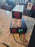

Please confirm this is how you have the wolverine wired to your power supplies and they are indeed floating supplies.
This youtube video may help
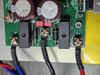
I see something connected to your heatsink. That's not necessary at this stage. Please disconnect that.
This youtube video may help
I see something connected to your heatsink. That's not necessary at this stage. Please disconnect that.
Attachments
Last edited:
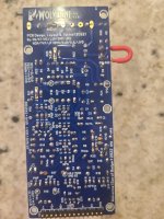
If that's 32v on the output of the Amplifier then you have a real problem. I can see some left over solder around that input board. You may want to check that the boards are cleaned properly. Did you double check that all your components are definitely orientated correctly. The fact that D10, D11 aren't lit its also a sign something is wrong. It maybe because you have no negative rail supply or maybe an issue with Q14 or Q12 maybe Q13 is it insulated properly.
I'm seeing 3 black wires and 1 red on the powers supplies and 1 black and 3 reds connected to the board. We need a picture that shows wires all way from powers supplies to the board. Pretty sure you have something hooked up wrong.
That's why I made the videoPretty sure you have something hooked up wrong.
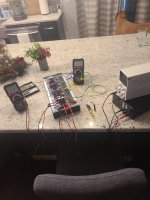
GND on PCB needs to go to 0 volts on PSU. From your image, if I interpret your wiring correctly it looks like you've got it connected the chassis (heatsink) only ....? That is, I mean it should be connected to the link you have between + and - on the PSU's, which becomes the 0V (as 90scaraudio explained in post 3304) ...
EF3-3 with 15K input impedance
Hello Wolverine team,
I would like to build my Wolverine with 15K as the input impedance. I have C1 and C9 with me with values 4.7uf and 220uf respectively.
What changes in the BoM need to be done against C2, R1, R9, R2, R21a and R21b to get 15K input impedance? Kindly advise.
Thanks
Sha
Hello Wolverine team,
I would like to build my Wolverine with 15K as the input impedance. I have C1 and C9 with me with values 4.7uf and 220uf respectively.
What changes in the BoM need to be done against C2, R1, R9, R2, R21a and R21b to get 15K input impedance? Kindly advise.
Thanks
Sha
@MilkyChance

I don’t know if the above pic helps you or anybody else. And btw, this Siglent power supply unit is excellent for +/- 32V or less.
Hope you get your unit all configured and fired up!
Best,
Anand.
I don’t know if the above pic helps you or anybody else. And btw, this Siglent power supply unit is excellent for +/- 32V or less.
Hope you get your unit all configured and fired up!
Best,
Anand.
Perhaps you could explain why its a good idea to connect the mains safety earth to the 0 volt rail.
- Home
- Amplifiers
- Solid State
- DIY Class A/B Amp The "Wolverine" build thread