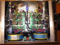
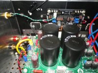
Excellent point! So eliminate the connection to the green terminal post that is chassis grounded correct?
Best,
Anand.
Best,
Anand.
Last edited:
The green terminal is not only connected to the chassis of the PS, its also running to the safety earth pin in the wall outlet. And from there interconnecting with various other equipment. The answer to your question; yes.
Trouble constructing your IPS board? Please read this:
Here are some suggestions about how to get your IPS board to amplify. The construction techniques used in constructing tube amps dont exactly apply to tiny PC boards. With some patient, expert help, I was finally able to learn a few things that were not obvious at the beginning. I hope these suggestions are helpful for someone.
1. You really do have to apply solder on both sides of the PC board.
I thought soldering the bottom traces alone would make a neater job and I could count on the through hole plating to conduct to the tracies on the top of the board. This was a mistake - it caused intermittents among other problems. You really need to solder both sides!
I wound up using nylon standoffs on both sides the board so I could solder the top then easily flip over to tack a little solder on the bottom of the hole. Stick a spacer underneath the leads of the components to push them up a bit before soldering the top. It was tempting to let the flat bottoms of some of the capacitors sit flush against the board but you can't solder the top side properly that way.
When you are soldering in the three transistor pairs (Q1,2;Q5,6;Q3,4), solder all six leads of the middle pair in first - that way you can access them easily. Soldering the bases of interior transistor of the two external pairs Q1,Q2 and Q3,4) is a bit of a challenge but it can be done with patience and a steady grip. For components with small gauge leads, you can sometimes get the solder to flow from the bottom to the top by inverting the board and tapping the bottom solder joint with the soldering iron tip; this did not always work and it made me nervous about overheating the component.
2. Set the impendence lead of the oscilloscope to X10!
Using the X1 setting, the trace flew off scale. Turns out that X1 loads the amp output down excessively. Must be that is what emitter followers are all about! 🙂 A 200 mV sine wave with X10 input gave a gain of about 10 with V+/V- 30V/-30V and a nice trace on the scope
3. You need an adequate V+/V- voltage
I was trying to be cautious by starting the V+/V- supply with +5/0/-5 then gradually turning the voltage up - I thought this would avoid damaging components that might be shorted. At these low voltages, I was getting only a V+ DC signal on NFB. Only when the applied voltage reached 20-25V per side was there amplification. If you feed it a 200 mV peak-to-peak signal, look for 2.5-3V out.
4 If you are approaching this amp from the world of Class A tube amps, concepts like long tailed pairs, constant current sources and cascodes may be new to you. They were sure new to me! These may help:
If you are approaching this amp from the world of Class A tube amps, concepts like long tailed pairs, constant current sources and cascodes may be new to you. They were sure new to me! These references may help:
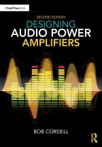
- Designing Audio Power Amplifiers, by Bob Cordell. Encyclopedic text on modern amp design. First few chapters have clear explanations of modern amp concepts.
There are some excellent You Tube explainers who really can help you. Here are some leading references.
#193: Back to Basics: the differential amplifier, aka long-tailed pair, diff-pair - YouTube Very clear description of long tail pair.
Differential Amplifiers Made Easy - YouTube – How a long tail pair rejects system noise.
#207: Basics of a Cascode Amplifier and the Miller Effect - YouTube Cascode amps
Hope this is helpful!
Here are some suggestions about how to get your IPS board to amplify. The construction techniques used in constructing tube amps dont exactly apply to tiny PC boards. With some patient, expert help, I was finally able to learn a few things that were not obvious at the beginning. I hope these suggestions are helpful for someone.
1. You really do have to apply solder on both sides of the PC board.
I thought soldering the bottom traces alone would make a neater job and I could count on the through hole plating to conduct to the tracies on the top of the board. This was a mistake - it caused intermittents among other problems. You really need to solder both sides!
I wound up using nylon standoffs on both sides the board so I could solder the top then easily flip over to tack a little solder on the bottom of the hole. Stick a spacer underneath the leads of the components to push them up a bit before soldering the top. It was tempting to let the flat bottoms of some of the capacitors sit flush against the board but you can't solder the top side properly that way.
When you are soldering in the three transistor pairs (Q1,2;Q5,6;Q3,4), solder all six leads of the middle pair in first - that way you can access them easily. Soldering the bases of interior transistor of the two external pairs Q1,Q2 and Q3,4) is a bit of a challenge but it can be done with patience and a steady grip. For components with small gauge leads, you can sometimes get the solder to flow from the bottom to the top by inverting the board and tapping the bottom solder joint with the soldering iron tip; this did not always work and it made me nervous about overheating the component.
2. Set the impendence lead of the oscilloscope to X10!
Using the X1 setting, the trace flew off scale. Turns out that X1 loads the amp output down excessively. Must be that is what emitter followers are all about! 🙂 A 200 mV sine wave with X10 input gave a gain of about 10 with V+/V- 30V/-30V and a nice trace on the scope
3. You need an adequate V+/V- voltage
I was trying to be cautious by starting the V+/V- supply with +5/0/-5 then gradually turning the voltage up - I thought this would avoid damaging components that might be shorted. At these low voltages, I was getting only a V+ DC signal on NFB. Only when the applied voltage reached 20-25V per side was there amplification. If you feed it a 200 mV peak-to-peak signal, look for 2.5-3V out.
4 If you are approaching this amp from the world of Class A tube amps, concepts like long tailed pairs, constant current sources and cascodes may be new to you. They were sure new to me! These may help:
If you are approaching this amp from the world of Class A tube amps, concepts like long tailed pairs, constant current sources and cascodes may be new to you. They were sure new to me! These references may help:
- Designing Audio Power Amplifiers, by Bob Cordell. Encyclopedic text on modern amp design. First few chapters have clear explanations of modern amp concepts.

There are some excellent You Tube explainers who really can help you. Here are some leading references.
#193: Back to Basics: the differential amplifier, aka long-tailed pair, diff-pair - YouTube Very clear description of long tail pair.
Differential Amplifiers Made Easy - YouTube – How a long tail pair rejects system noise.
#207: Basics of a Cascode Amplifier and the Miller Effect - YouTube Cascode amps
Hope this is helpful!
Why the through hole plating isn’t enough to connect the top and bottom traces ?
I used to solder only the bottom trace and I haven’t any problems until now.
I used to solder only the bottom trace and I haven’t any problems until now.
This isn't uncommon for duallayer PCB's, don't ask me why🙂 It's good practice to solder each side or at least make sure that solder has reached both sides and made good connection.
I follow a "dude" that sells DIY on Instagram. He also posts the returns from people who gave up their project and return to him as not functioning.. Most of the time it's just missing solder on the topside that's missing and the board works afterwards.
There's some good advices from @lotharx I think
Last edited:
You must have been applying enough solder to the bottoms and not depending on the through holes for high current transfer. Some of the traces on the tops of the boards are pretty wide and there is not a lot of gold in the through holes to feed them. That's what the vias are about! In my experience, bottom soldering worked most but not all of the time.Why the through hole plating isn’t enough to connect the top and bottom traces ?
I used to solder only the bottom trace and I haven’t any problems until now.
Τhese days I found some time to upload the Ussa5 to the Wolverine site and do some acoustic tests. The Ussa5 sounds more detailed and with more stereophonicity, it also has no capacitor at the input. I will also try Wolverine without a capacitor at the input and compare again. Has anyone tried the same thing to play Wolverine without input capacitor?
Attachments
Last edited:
You'll lose your input DC-protection when removing the cap, and I don't think anyone here would recommend it. If your preamp is also capfree, this approach is somewhat for the "brave" as you'll have no safety net besides form hopefully a speaker protection relay of some sort...!?
Instead of desolderin the cap, add some pinheaders to the PCB to form a jumper that can easily bypass the cap and visa versa without the need to head up the solderingiron. That's how I would do it anyway..
I don't think you will hear much of a difference, but I know the feeling for tryouts.
Instead of desolderin the cap, add some pinheaders to the PCB to form a jumper that can easily bypass the cap and visa versa without the need to head up the solderingiron. That's how I would do it anyway..
I don't think you will hear much of a difference, but I know the feeling for tryouts.
Has anyone put a volume potentiometer on their Wolverine?
I was thinking of connecting it directly to my DAC and not using a preamp.
How many K should the pot be?
Here is one I was looking at,
https://www.aliexpress.com/i/1005001638516873.html
Any suggestions for a good stepped potentiometer?
I was thinking of connecting it directly to my DAC and not using a preamp.
How many K should the pot be?
Here is one I was looking at,
https://www.aliexpress.com/i/1005001638516873.html
Any suggestions for a good stepped potentiometer?
Last edited:
Nice to see a video covering it... however, I got 5 minutes in and I'm cringing a bit over the explanation of the circuit. A lot of misinterpretations. Calling the Cap Multiplier a voltage regulator and indicating the that IPS output comes from the CCS input.
Has anyone put a volume potentiometer on their Wolverine?
I would think that you'd want to look at the values for the RC filter formed by R1 and C2. If you're using a passive source with a higher output impedance, these may need to be adjusted to prevent early roll-off.
Passive preamps suck big time. They just sound so anemic sucking life out of music. Use buffer or use normal pre with normal output impedance and you can put any pot on the amps input, from 10k to 100k, no change in fr response.
Has anyone put a volume potentiometer on their Wolverine?
I was thinking of connecting it directly to my DAC and not using a preamp.
How many K should the pot be?
Here is one I was looking at,
https://www.aliexpress.com/i/1005001638516873.html
Any suggestions for a good stepped potentiometer?
https://sound-au.com/project01.htm
I've done the very basic one, 100k pot and a 12k resistor. It works.
Any suggestions for a good stepped potentiometer?
DaveFred:
Consider this as an alternative: https://www.aliexpress.us/item/3256...sea!US!1746454576!&curPageLogUid=eSrrWEvp1JY0. I've used them to great effect, including in an integrated Wolverine amp project.
I agree with adason -- the concept of passive preamps ("just an attenuator!") is far more compelling than the reality. I've built a few and none of them had the sense of space and air that breathes life into music. Don't cripple your Wolverine by adding just a potentiometer.
How about this: PM me your address and I'll send you a pair of RJM Audio B-buffer boards, gratis. The B-buffer works really well, is inexpensive to build and I have an extra set. You'll need to add a second lower-voltage power supply to your project (though as I think about it, you'd need one anyway if you're planning on relay-based source selection). If you lay out the design with care there should be plenty of room in your chassis (see, for example, my layout: https://www.diyaudio.com/community/...rine-build-thread.385920/page-24#post-7114011).
Regards,
Scott
Hi Guy’s,
Myself and a few other Wolverine team members are getting an increasing number of requests for EF3-4 boards. While we plan to release an updated version of the Wolverine PCB’s sometime in the new year, possibly March / April to address a few minor things, there may or may not be any performance improvement with the new boards.
At the moment we feel that it might be time to hold a limited Group buy for IPS and EF3-4 boards only. So those people who would like to build something over the holidays have an opportunity to do so.
The boards would be exactly the same as the current 2nd GB boards which was Version 3.8 for the IPS and Version 4.0 for the output stage boards. We do still have a number of EF3-3 board available for anyone who is interested in those as well. We would run a single colour, most likely Green or Blue. The most popular from the forum members orders would be selected. The Group buy will be open for a week. It will close on the 19th of December so if you would like any boards, please send your Order form (follow the link below to the 2nd group buy) to Stuartmp@internode.on.net
@jjs (Jeremy) is busy over Xmas so @fireanimal (Andy) and I will handle the distribution of boards.
We will touch base will all the people who sent enquiries or order forms to check they are ready to go ahead. So, if you don’t hear from us in a few days, please resend your order form which is attached to the 1st post of the 2nd group buy thread.
Last edited:
Just an fyi if you are testing your build with the outputs installed and everything test out except you have positive 50 vote on the outputs ck if you left the 9.11K resistor under R17 on your ips board. I got distracted from the build and came back to it and did not remove it or lower the bias. It blew the 2A fuse on the negative rail and when I dialed back the bias I had 52 volts on the output. Removed it everything test to spec and enjoying it in the living room now.
Bill
Bill
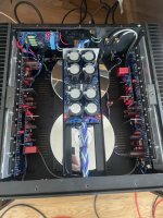
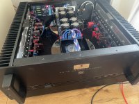
Been listening for over a month now, happy to report my amp all working 100% and I see no reason to ever replace it. I love it. Happiest I've been with my system for a long time. Speaker protection from @felix1024 has arrived so that's this holidays project.


Be aware that it needs a bit work, as published it wont detect negative DC, and during it's use of the Delay() Function, it wont detect anything at all.
- Home
- Amplifiers
- Solid State
- DIY Class A/B Amp The "Wolverine" build thread
