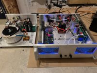
Testfitting of my (partly stuffed) own made boards - 3HE Modushop case needs some modification if you want to use ceramic insulators...


Truly DIY to pick up the challenge to self design the PCB. What software did you use? Did you make a mirrored set?
I found it was necessary to build a frame beneath my 1 kVA toroidal transformer in order to stabilize it. It was quite a squeeze to fit everything in my 300 deep 4HE cabinet. Will follow your build with interest.
I found it was necessary to build a frame beneath my 1 kVA toroidal transformer in order to stabilize it. It was quite a squeeze to fit everything in my 300 deep 4HE cabinet. Will follow your build with interest.
They're designed with KiCAD. The version you can see in my last post is following 1:1 the groupbuy-board (plus the latest feedback path improvement). I've done a mirrored layout, too. But that was not in production yet.
Hello,
I have just done initial power up and i dont get the expected voltage across TP107 / TP108.
According to the guide i should read between 750 mV to 800 mV but i get 900mV.
i am using a +/- 35V lab PSU with current limit to 0.3A. it is not limiting
For information i am using an old BOM with R109 = 200 Ohms
D10 and D11 light only a short time at startup. All others keep lighting.
When i change R109 voltage increase so do you think that's OK ? should i continue or look for something wrong ?

Slowly finishing the project, one technical question: why Q9 and Q10 are high voltage KSA992? Q9 and Q10 have C-E voltage of about 1.2V. Wouldn't be better to use a lower C-E voltage but higher collector current transistors such as KSA1015 or alike?
Those are current sources, and the voltage at the base of Q8 and Q11 is set by 2*Vbe this cant be changed without a modification of the circuit. Since the chosen setup gives excellent results there is no reason to change it.
2 GB EF3-3 board @ 57v rails
I'm finally finished!!🙂
First I have to say that this amp is absolutely fantastic. It really is!
I would like to say how important it is that if you decide to build this, you need a LARGE CASE and LARGE HEATSINKS!!!
This should be stressed at the very beginning of the build. It may give a little pause.
I did not pay much attention to this important fact and I purchased a small chassis and way to small heatsinks, I didn't know as I was going by normal home audio stereo's that I've repaired in the past.
I did get large heatsinks that completely filled the chassis and it left little room for the 800va toroid. Turns out the toroid was just to close to the amp boards and was picking up some hum.
I decided to get a separate chassis for the PS which did solve the hum problem. Sure wish I purchased the large chassis from the DIY store!
The Toroid is an AnTek 800VA 40-0-40 with a 12v and 18v output option. Specs are 10Amp x 2. Also from AnTek, they sell a soft start module and a full wave bridge with a 90kuf filter bank with a built in bleeder circuit. Not bad.
I removed two of the 15kuf caps and installed them in the amplifier chassis.
The wire used from the PS to the amp is about 12 inches long and is 10awg.
Inside the amp is 12awg to the boards
I used Elliott Sound Products Better Volume Control using 100k pots with a 10k resistor. I did this just for some control on the input.
The VU meters are driven from the speaker outputs to a circuit I built that was used in a Yamaha CA-610 II. It does not require power other than the speaker output. I did modify the high power portion of the board so the VU switch can read more than 50watts. It now measures about 180 watts. The low end is still set for about 2 watts.
The outputs are ONSEMI MJL1302A MJL3281A from NEWARK Electronics.
I did spend much time designing the layout so it can be easily disassembled for service.
I hope this can help someone that is thinking about building this project. BUY THE 5U CHASSIS WITH THE HEATSINKS!!! Save yourself lots of time...
OK... Now to enjoy the wonderful amplifier... You guys are awesome... Thanks
Scott
Attachments

I would like to see the BOM to see what parts I have already. Then I can determine if its Feasible Cost wise.
Parts to populate boards from BOM ordered this week for 3 pair board, around $700.00 CDN delivered with taxes from Mouser in Canada (about $500 USD, but your prices aside from currency conversion might be different). Not including boards, chassis, power supply and misc sundries.
Well done Scott !2 GB EF3-3 board @ 57v rails
I'm finally finished!!🙂
First I have to say that this amp is absolutely fantastic. It really is!
I would like to say how important it is that if you decide to build this, you need a LARGE CASE and LARGE HEATSINKS!!!
This should be stressed at the very beginning of the build. It may give a little pause.
I did not pay much attention to this important fact and I purchased a small chassis and way to small heatsinks, I didn't know as I was going by normal home audio stereo's that I've repaired in the past.
I did get large heatsinks that completely filled the chassis and it left little room for the 800va toroid. Turns out the toroid was just to close to the amp boards and was picking up some hum.
I decided to get a separate chassis for the PS which did solve the hum problem. Sure wish I purchased the large chassis from the DIY store!
The Toroid is an AnTek 800VA 40-0-40 with a 12v and 18v output option. Specs are 10Amp x 2. Also from AnTek, they sell a soft start module and a full wave bridge with a 90kuf filter bank with a built in bleeder circuit. Not bad.
I removed two of the 15kuf caps and installed them in the amplifier chassis.
The wire used from the PS to the amp is about 12 inches long and is 10awg.
Inside the amp is 12awg to the boards
I used Elliott Sound Products Better Volume Control using 100k pots with a 10k resistor. I did this just for some control on the input.
The VU meters are driven from the speaker outputs to a circuit I built that was used in a Yamaha CA-610 II. It does not require power other than the speaker output. I did modify the high power portion of the board so the VU switch can read more than 50watts. It now measures about 180 watts. The low end is still set for about 2 watts.
The outputs are ONSEMI MJL1302A MJL3281A from NEWARK Electronics.
I did spend much time designing the layout so it can be easily disassembled for service.
I hope this can help someone that is thinking about building this project. BUY THE 5U CHASSIS WITH THE HEATSINKS!!! Save yourself lots of time...
OK... Now to enjoy the wonderful amplifier... You guys are awesome... Thanks
Scott
- Dan
@90scaraudio, you are right about the case size. I have the EF3-3 in a 4U case with 300mm depth (like the Deluxe 4U) and everything fits in nicely without too much space to spare. I wouldn't dare make it smaller than that. Heatsinks are a little oversized though. They get barely warm.
I think you have to buy the boards to get the BOM. Unless the designers would send them to you. I did spend some cash getting parts from mouser, maybe around $400. I do have a lot of parts but you will still need to get some tight tolerance resistors and a bunch of transistors. I had to closely match some of the transistors so this is the reason to buy about 10 or 20 ea. If you do get the boards, you can take your time to build them. Get the parts a little at a time so it doesn't hurt the wallet so bad. The Chassis is the biggest thing to purchase... It comes predrilled for the boards and gives plenty of room for the transformer, (s). I made the mistake and thought I'd spend less on the chassis, I ended up having to get another chassis and another set of heatsinks so It cost me the same as the 5U chassis from the DIYSTORE! Please don't make this mistake like I did. I did a lot of drilling, cutting and filing on mine and made for a lot of time spent in the garage.I would like to see the BOM to see what parts I have already. Then I can determine if its Feasible Cost wise.
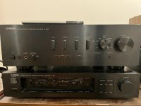
This amp does sound better than my Kenwood Basic M2. And better than this Yamaha A-S801. That's saying a lot as I really like the Kenwood.
Attachments
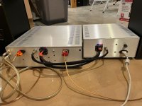
Does my troid transformer (audio grade Toroidy) need to be any certain distance from the sides of the chassis? Any problems caused by being too close to a side?
Hello Gents,
Bin a while as I've moved to a new house. Buyer of the old house hasn't come through with payments so a bit of lawsuit going on here...😒.....
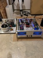
After running the beast for a couple of months...I thought I'd give her a component inspection and do some measurements. No obvious failures besides some dust🙂
Offsets, bias and current source look reasonable I suppose besides the AC offset of the left channel which reads 12 mv. I did not shortcut the input on either measurement by the way...
bias right channel

ac offset right channel

dc offset right channel

constant current

ac off set left channel

dc off set left channel


bias left channel


Bin a while as I've moved to a new house. Buyer of the old house hasn't come through with payments so a bit of lawsuit going on here...😒.....
After running the beast for a couple of months...I thought I'd give her a component inspection and do some measurements. No obvious failures besides some dust🙂
Offsets, bias and current source look reasonable I suppose besides the AC offset of the left channel which reads 12 mv. I did not shortcut the input on either measurement by the way...
bias right channel
ac offset right channel
dc offset right channel
constant current
ac off set left channel
dc off set left channel
bias left channel
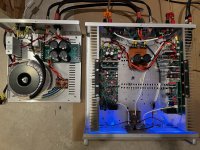
One thing I noticed when setting the bias is... if I continue to monitor the bias and put the lid on the chassis, the 44mv bias starts to drop. It goes down to about 30mv or so...
So what I've done is adjust the bias to about 50mv with the lid off and watch it with the lid on. I'll keep doing this until it settles at about 44mv with the lid on.
I think this is the correct way to set it.
Scott
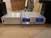
Nice Chassis wkloppen...
So what I've done is adjust the bias to about 50mv with the lid off and watch it with the lid on. I'll keep doing this until it settles at about 44mv with the lid on.
I think this is the correct way to set it.
Scott
Nice Chassis wkloppen...
Completed the amplifier. It's such a wonderful sounding unit. Maybe after the breakin it's just going to improve.


- Home
- Amplifiers
- Solid State
- DIY Class A/B Amp The "Wolverine" build thread