You don't need to drive bias up to 100mA. Cross distortions will be small enough with 75-85mA and the amp will run a bit cooler. The so called "optimum" depends on many factors and consequently the choice of "optimum" bias becomes subjective. Best listen to your favorite music at different bias levels including higher than 100mA bias and decide by yourself. I do not think anyone would be able to tell apart 100mA bias from 80mA bias. Below bias examples of some commercial AB class amps (taken from another DIY thread):One thing I noticed when setting the bias is... if I continue to monitor the bias and put the lid on the chassis, the 44mv bias starts to drop. It goes down to about 30mv or so...
So what I've done is adjust the bias to about 50mv with the lid off and watch it with the lid on. I'll keep doing this until it settles at about 44mv with the lid on.
I think this is the correct way to set it.
Scott
Nice Chassis wkloppen...
Sony TA-N77ES 15mV // 0.47E
Sony STR-DA50ES 6mV // 0.22E (SAP15)
Denon AVR-1909 2mV // 0.47E/2
Rotel RB1090 5mV // 0.22E
Rotel RMB1095 5mV // 0.22E
Harman Kardon AVR366 26mV // both emitter resistors (0.27E * 2)
cheers,
Last edited:

OK, did not know this... It would keep it a little cooler... I'll try it. ThanksYou don't need to drive bias up to 100mA. Cross distortions will be small enough with 75-85mA and the amp will run a bit cooler. The so called "optimum" depends on many factors and consequently the choice of "optimum" bias becomes subjective. Best listen to your favorite music at different bias levels including higher than 100mA bias and decide by yourself. I do not think anyone would be able to tell apart 100mA bias from 80mA bias. Below bias examples of some commercial AB class amps (taken from another DIY thread):
Sony TA-N77ES 15mV // 0.47E
Sony STR-DA50ES 6mV // 0.22E (SAP15)
Denon AVR-1909 2mV // 0.47E/2
Rotel RB1090 5mV // 0.22E
Rotel RMB1095 5mV // 0.22E
Harman Kardon AVR366 26mV // both emitter resistors (0.27E * 2)
cheers,
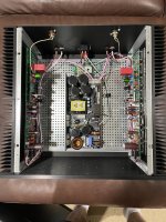
Offsets, bias and current source look reasonable I suppose besides the AC offset of the left channel which reads 12 mv.
What could be the reason of the relatively high AC offset only on the left channel? Could that be position / rotation angle of one of the transformers? Or the slow start circuitboard mounted on the rear panel above which the left channel input cable is running?
thx for any tips...
Hi Wkloppen,
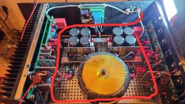
Maybe try moving the signal input wire which is running past the soft start board on the back panel.
This is just a guess but maybe the small transformer is injecting some hum into the left channel via the signal input lead.
I had a similar problem once on a different amplifier with < 1 mV AC on the output with no signal and rotating the toroid about 45° fixed it.
I hope this helps.
- Dan
That's probably it. Disconnected the left channel input cable and shorted it with wire. Now it measures pretty much in the ballpark I guess with an AC offset of 0.03 mv and a dc offset fluctuating slowly between - 0.2 and + 0.2 mv. Need to reroute the left input cable🙂Maybe try moving the signal input wire which is running past the soft start board on the back panel.
AC
DC
Maybe moving the soft start board is a better option. Will it fit on top of your toroidal transformer.Need to reroute the left input cable🙂
Maybe moving the soft start board is a better option. Will it fit on top of your toroidal transformer.
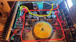
Nice tips.....on top of the transformer wouldn't fit I think. Unfortunatly the consequence of having 2 seperate transformers instead of one. I'm thinking of fabricating a bracket for the soft start placing it perpendicular on the backpanel while on the same time moveing it a bit inwards inbetween the 2 PSU's.down the top of the right side would put it next to the outputs.
I will first meansure the relation between distance and the measured offsets. Maybe a move of only 2 cm makes all the difference🙂
w.
Thats an option for sure but I might increase the noise by moving it closer to one of the channels. Could work though....Need to test it first and I'm a bit reluctant to disassemble a nice working amp🙂. Will mkae a test left channel input wire first to get a feel of the distance required.move the trafos a bit on the left or on the right
In this case I prefer iron pipe as braided copper does not help much against the magnetic field coming from the auxiliary transformer.
Remove the cable from the RCA socket and away from the soft start. Do some measurements and if there is no noise/ hum, move the RCA socket to the other side.
I would prefer this route for the input wires.
Rearrange both input wires and keep those close to the bottom of the enclosure.
I prefer to use pcb pins and solder the input wires too.
Rearrange both input wires and keep those close to the bottom of the enclosure.
I prefer to use pcb pins and solder the input wires too.
Attachments
Last edited:
The best part of the job is slowly coming to the end.
I would do the same. I prefer keeping RCA sockets close to their respective boards, less noise problems.Remove the cable from the RCA socket and away from the soft start. Do some measurements and if there is no noise/ hum, move the RCA socket to the other side.
- Home
- Amplifiers
- Solid State
- DIY Class A/B Amp The "Wolverine" build thread