It's strange, even if you did scrape the cost off, pads should remain isolated, while there it seems that there is still some solder...
If i deal with bridge like this, i heat it till liquid and take sharp screwdriver to separate the pads.
Wick braid can be tricky to use. You might apply a bit more solder to the bridge and then retry the wick. You have to turn the iron temperature up a good bit and then press hard with the iron. If the solder mask is gone you may have to use "mechanical means" such as an xacto knife to push the errant solder away. Another thing that might work is to add some solder flux to the area before you use the wick. Some solder wicks have flux pre applied.
@stuartmp glad to see you adding a note about the DC offset not always working in low voltage testing.
One additional testing option I'll point out is that if you want to test the whole voltage amp/drivers chain without the output transistors, leave out C113. Doing that allows the entire chain to be tested for full voltage swing. With C113 in the circuit there is too much load on the drivers to get a full swing at higher frequencies on the Vout net.
I ran into both of these issues when trying to troubleshoot a board set I did for someone else. Turns out there was no problem, just my test assumptions.
Hi Stuart and Daniel and Mainframe-
Thanks so much for the advice! I figured I would do a little more measuring before trying to swap resistors. Strangely, as I was probing R17 with my VMM leads, the LEDs D10 and D11 came on for the first time. Don not understand this at all.
In any event, the voltage drop across R17 is 16.5V. I measured it 9.9K so by Ohm's law, it must be passing 1.6 mA, which seems low.
With +30V/0/-30V, the NFB/PD+/ND- is 29.8V.
Measuring each output separately (jumpers removed),
NFB = 400 mV (not sensitive to adjusting R25)
PD+ = 29V
ND- = -65 mV (this moves around while I watch it)
So somehow, the V+ is leaking into PD+
Does this clarify anything?
Jon
Nice find, I'll discuss this will the other guy's and see if we should include a note about this for people who own a oscilloscope and want to verify the entire circuit with a full voltage swing test.@stuartmp glad to see you adding a note about the DC offset not always working in low voltage testing.
One additional testing option I'll point out is that if you want to test the whole voltage amp/drivers chain without the output transistors, leave out C113. Doing that allows the entire chain to be tested for full voltage swing. With C113 in the circuit there is too much load on the drivers to get a full swing at higher frequencies on the Vout net.
I ran into both of these issues when trying to troubleshoot a board set I did for someone else. Turns out there was no problem, just my test assumptions.
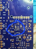
I only use Gootwick 2.0mm for this sort of thing. I have found other brands simply don't work.Can this bridge be fixed?
In your case its not a problem as all those pads share the same net. Check the other side of the board and you'll see

Hi Guys,
I have updated the Build Guide, Current revision is now 39.
Revisions are noted at the end of the document.
I have updated the Build Guide, Current revision is now 39.
Revisions are noted at the end of the document.
As other mentioned, adding more solder might help keeping the iron at high temperature and a soldersucker. Also solderwick, although I do not find it suited for all applications. Sometimes adding some liquid flux to the braid helps if absorb the solder better.Can this bridge be fixed?
If any of these don't work, I normally cut the excess of with a sharp knife/scraping tool before the solderpads is to beaten up by heat and ect from other tryouts...
EDIT: I see now that @stuartmp has posten that the pads are connected🙂
Hi Jon, In your photo you are actually measuring across R15 and with 30v Rails 1.6mA is correct.In any event, the voltage drop across R17 is 16.5V. I measured it 9.9K so by Ohm's law, it must be passing 1.6 mA, which seems low.
It looks like you are running 57v rails so I have made you a schematic for testing "Wolverine IPS Only 30v Rail testing - with 57v full voltage rail components"
I also added this file to the Dropbox folder along with a 64V version "Wolverine IPS Only 30v Rail testing - with 64v full voltage rail components"
See attached
You 100% do not want to separate those connections. They need to be in place otherwise the circuit is not complete and you will have no negative feedback.Measuring each output separately (jumpers removed),
Please reconnect them as shown in the IPS isolation testing section and test and varify the voltages shown on the attached schematic.
Please come back with a marked up copy of the schematic showing the voltages you are measuring and there values.
Attachments
I am leaning more to doing something like this.Edit - OR , use the 2 included (working) 300W SMPS's - real cheap !!
Maybe doing a build with the 8 outputs and the big transformer and caps.
Trying to keep it pretty cheap.
All in all. It was 60 bucks with shipping. But If I can get the smps and case plus the boards and BOM, it should come out pretty cheap. Reading more and more into the build, and I am getting pretty excited about building this thing!PS - what a deal for 28$ , I did not know what was in the cases ???
Case is too small , 6 OP just fits.Maybe doing a build with the 8 outputs and the big transformer and caps.
Then you would need that $200 dissapante DIYA chassis and 150$ antek , that's what I avoided.
OS
Quick Question, I'm not an engineer!!! Is it going to be OK to use MJL3281AG/1302AG with +-56v rails?
Scott
Scott
- Home
- Amplifiers
- Solid State
- DIY Class A/B Amp The "Wolverine" build thread