Post number 2057, as Stuart links above, is the way. Thanks Andy/fire animal

Ok , I see clearly. Thanks for those professional tests.
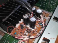
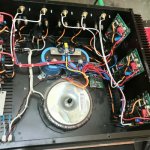
I have a picture of the very original Wolverine EF3 (HK680- below).
I just copied the Vbe , as I never built any previous EF3's.
Left circle is HK's (Q104) , and the right circle is Q103 + 2SC4793/A1837.
They use 2SC3423-Y as Vbe (2X). I own the HK , it is rock solid , thermally.
I have not personally ordered my new EF3's , might redesign the whole circuit.
Might go with a ambient Vbe using the "leach" 4 diode method to establish the ratio.
Diodes don't have Hfe AND Vf , just Vf vs. temperature.
I'll use my other Wolverine board as a "guinea pig" for this new Vbe.
OS
Attachments
Just a wild guess, but maybe the presence of Rcc in the Wolverine circuit forced an over-compensation that was too much. I see there is none in the HK680.
A quick question, maby it has been answered in this thread -but can't seem to find info in the BOM or build guide??
How many spacers do I need for the main EF3-4 board to heatsink.
I buying a chassis from modushop that hasn't been precut due to MT200 outputs.
I found these male/female (M3)10mm length on mouser, but how many should I add to the basket? 🙂 and is 10mm ok?
https://www.mouser.dk/ProductDetail/Keystone-Electronics/24337?qs=UWqYQ/2cZWuMPEm0DiFF0w==
Regards
Last edited:
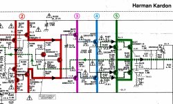
Since Rcc subtracts Vbias current changes ... "it is added to give first-order cancelation of Vbias variations caused by VAS current changes" (SELF ch.15) ,Just a wild guess, but maybe the presence of Rcc in the Wolverine circuit forced an over-compensation that was too much. I see there is none in the HK680.
it would increase compensation.
It is surprising HK does not use it , since the 680 is not a current source based VAS ??
The Wolverine is - it's topology has the most stable VAS Ic.
Vbias calculations can be modeled , but rarely exactly reflect the real world.
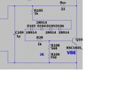
Ideal is a temp-co sensor with 4 junctions that would be the exact inverse of the driver/output junctions. Like the ON "thermaltrack" (NJL3281).
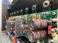
Here we have MUR120 integrated with a NJW0281 . I've seen a few modern "leach amp" EF3's that tested spectacular with this arrangement. (below).
Also , I have no base-stoppers (jumpered) on my drivers ? Why , did it oscillate ?
I am running TTC004/2SC4793/2SC3519 (sanken) as EF3. Close to the HK.
Devices will determine the tempco. You would nearly have to offer multiple values(BOM) to compensate for different devices.
PS - I ordered 10 MUR120 SMD's , I like "tinkering"....
OS
Attachments
Folks:
Here's where I am with my Wolverine repair:
Following Stuart's guidance, I pulled the "bad" Wolverine channel (I will pull the good channel if need be) and resoldered every joint on the EF3-3 (v 3.9) and IPS boards. After downloading the latest Build Guide (v 35) I started testing the two boards per the Build Guide at Section 20.A. The results:
Sec 20.A - 20.D followed instructions
Sec 20.E - 0 mV output bias measured across TP-101 and TP-102
Sec 20.F - 0 mV bias voltage measured at power up (and no further change after 5 minutes)
Sec 20.G - 5.20 V measured across TP-1 and TP-2, adjusted down to 5.0 V
Sec 20.H(i) - DC offset across TP-104 and TP-100 adjusted to 0.0-0.1 mV after 10 minutes
Sec 20.H(ii) - measured 0.000 VAC across TP-104 and TP-100
Sec 20.J - measuring 0 mV across TP-101 and TP-102, tried adjusting R109. Lots of rotating and no change to the measurement across TP-101 and TP-102
Please advise.
Thank you (again) for the support!
Regards,
Scott
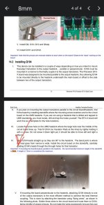
Check section 14.2How many spacers do I need for the main EF3-4 board to heatsink.
Attachments
BOM and Build Guide in Post #1.A quick question, maby it has been answered in this thread -but can't seem to find info in the BOM or build guide??
8 per board 10mm is what you need. Female female. I prefer the stainless steel or brass over aluminum.How many spacers do I need for the main EF3-4 board to heatsink.
Hey all.. I have lurked for quite a while but throwing myself into the pack. Lol. fireanimal was super kind enough to set me up with a head start on this amplifier and while my experience in electronics is pretty extensive, it’s more in the digital domain, microcontrollers and digital circuits and my RF experience is all 1ghz and above, but I do love my music to sound great!
So sort of an intro post and was curious if anyone knew how many members are active or have completed their builds?
So sort of an intro post and was curious if anyone knew how many members are active or have completed their builds?
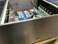
Fire , what SMPS ? I'm at the trafo purchase point , debating whether to buy into all that poundage...
I see you have large caps powered by the SMPS .. no issue ??
OS
I see you have large caps powered by the SMPS .. no issue ??
OS
Thanks for the answer👍 I did add stainless to the basket at first, but later spotted the alu-version due to pricetag... Might change back this after your answer8 per board 10mm is what you need. Female female. I prefer the stainless steel or brass over aluminum.
Regards
And to tack on a follow up for @fireanimal
Do you suspect 2x10,000uF output per rail on the Cobra is sufficient?
Do you suspect 2x10,000uF output per rail on the Cobra is sufficient?
https://micro-audio.com/store/product/cobra-s1/Fire , what SMPS ? I'm at the trafo purchase point , debating whether to buy into all that poundage...
I see you have large caps powered by the SMPS .. no issue ??
OS
It is a cobra S1/S2, I also used these to power my EF3-3 builds I did, and they have been running now for almost 15 months without issue.
The 20k per rail is sufficient, I never added any additional caps on my EF3-3 builds.
Hi Scott,Sec 20.J - measuring 0 mV across TP-101 and TP-102, tried adjusting R109. Lots of rotating and no change to the measurement across TP-101 and TP-102
Everything looks like it tested out ok except the output bias appears to not be increasing.
Just checking that you re set your meter to DC as the previous measurement was AC.
If it was dc was it in the mV range?
Depending on which way you installed R109 you need to turn the trimpot so that the resistance reduces to increase the bias.
If you turn the board over you'll see the pin numbers. You want to reduce the resistance between pins 1 & 2 please confirm that what you we're doing. Maybe send a photo and indicate what direction you're turning to confirm.
Last edited:
Wow , pricey !! $330 - wow ! MUST be nice...https://micro-audio.com/store/product/cobra-s1/
It is a cobra S1/S2, I also used these to power my EF3-3 builds I did, and they have been running now for almost 15 months without issue.
The 20k per rail is sufficient, I never added any additional caps on my EF3-3 builds.
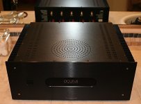
For $99 + 50 shipping , I might get the whole case/trafo ... everything (below).
I'd use modern PS PCB's instead of those old electro's.
OS
Attachments
- Home
- Amplifiers
- Solid State
- DIY Class A/B Amp The "Wolverine" build thread