Hi Guy's, The build guide was updated. Current version is now 37.
The first post and the Dropbox folder has been updated with the latest version.
Revisions are noted in the revision section at the end of the document.
The first post and the Dropbox folder has been updated with the latest version.
Revisions are noted in the revision section at the end of the document.

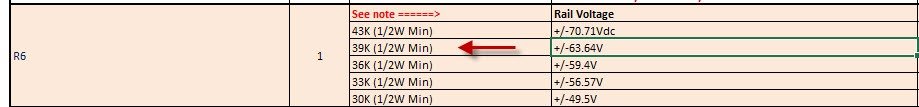
Your calculations are correct however for 68V rails I would probably use the values shown for 64V rails rather than the 70.71V values as slightly more current there will ensure the forward current for the LED is past the Knee point. They are marked in the BOM as 1/2W. There are other reasons to use a 1/2w package. In that location 1/2W is preferable over 1/4Wquestion on R6 (43k) resistor - no mention like other resistors in THE BOM it needs to be 1/2w, but the parts listed are 1/2w. I have 1/4w on hand, so I want to make sure I'm not setting myself up for a failure using a lower wattage part?
Can I use 1/4w or do these need to be 1/2w? Also in the process of a c4793/a1837 conversion to MJE drivers.
Ohms law calculator is giving me 110mW, assuming 68V across 43k at ~1.6mA - so I think I'm good with 1/4w resistor, but can anyone confirm for me?
Attachments
Super excited to finally be starting my build!
Just wanted to say that the boards are absolutely beautiful. Have never seen such professional DIY boards before.
Got the EF-4 boards and will probably go for a 70V power supply. Though i'm having a bit of trouble deciding how exactly i should do the power supply...
Does @fireanimal still sell finished heatsinks?
I'm using the GB 1 BOM from May 29th and it doesn't have 1/2w - but I do see it is notated in the GB 2 BOM from the same date (note to self - check GB2 docs for most accurate). Thanks for the answer and I will change this back to a 39k 1/2w to ensure safety and accurate current flow.Your calculations are correct however for 68V rails I would probably use the values shown for 64V rails rather than the 70.71V values as slightly more current there will ensure the forward current for the LED is past the Knee point. They are marked in the BOM as 1/2W. There are other reasons to use a 1/2w package. In that location 1/2W is preferable over 1/4W
Brings up another question: I just changed both input boards for +/-70Vdc (since my PSU varies from mid-68 - low-69Vdc) and updated R6, R15, R17, R23 and R24 along with updates to change the drivers to MJEs last night. Was able to get Channel 1 updated, burned in and playing great, and the updates done to Channel 2, but not enough time last night to set-up and burn in, so I was planning to do that this evening.
Before I do - I will change R6 back to 39k 1/2w from the 43k 1/4w currently installed - as Stuart provided earlier.
Does this mean I need to go back for R15, R17, R23, R24 to the original values for 64Vdc rails, instead of the updated 70V rail values I changed to? I want the amp to be reliable once I get all these updates/fixes completed.
Yes, I would encourage you to use the values for 64v rails.Does this mean I need to go back for R15, R17, R23, R24 to the original values for 64Vdc rails,
Please ensure R17 is mounted adequately above the pcb as recommended in the build guide.
Sure glad the silkscreen was correct!!! That could have been a blunder...Thanks for catching that.Hi Guy's, The build guide was updated. Current version is now 37.
The first post and the Dropbox folder has been updated with the latest version.
Revisions are noted in the revision section at the end of the document.
Thanks Stuart - I have made the 64V rail updates to both boards and they are currently "burning in". I will be listening to some music again very shortly. Thanks, as always, for the support and being a phenomenal resource.Yes, I would encourage you to use the values for 64v rails.
Please ensure R17 is mounted adequately above the pcb as recommended in the build guide.
I’m having a ******* spiritual experience listening to this amp.
This is what i have been searching for in my system.
First DIY amp, and what the hell have I been missing.
This is like my first set of hifi speakers all over again. I’m so happy. All the audiophile cliches at once.
This is what i have been searching for in my system.
First DIY amp, and what the hell have I been missing.
This is like my first set of hifi speakers all over again. I’m so happy. All the audiophile cliches at once.
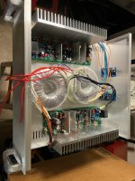
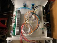
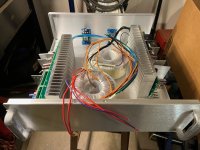
Purchased a 16 x 16 x 5 inch with handles for about $115 with shipping from Par metals. Nice chassis.
The Toroids I purchased have a shield that has a purple wire that gets chassis grounded.
Question for installing all this for the least amount of possible noise or should I not worry about it to much?
See Pics.
Thanks all...
The Toroids I purchased have a shield that has a purple wire that gets chassis grounded.
Question for installing all this for the least amount of possible noise or should I not worry about it to much?
See Pics.
Thanks all...
Attachments
Making me even more excited to finish my build..!I’m having a ******* spiritual experience listening to this amp.
This is what i have been searching for in my system.
First DIY amp, and what the hell have I been missing.
This is like my first set of hifi speakers all over again. I’m so happy. All the audiophile cliches at once.
What is your Wolverine “superseding” if you don’t mind me asking?
I was previously using a Perreaux E200 for about 2 years, and before that a yamaha mx1 for a couple, before that a naim (cant remember the model, 250? maybe), also had a 6 month period with a ncore setup. I understand expectation bias, but the truth is I hoped with the wolverine I wouldn't have any. I am firmly in the amps all sound the same camp. Heck I even ran a TP3255 chip job in the main system for a couple months, with no complaints. But I had to pick my jaw up off the floor with this amp, I am just taken back by the depth and cleanness of this amp. I have never ever heard a top end so .. clean. The decay, the separation, I even switched back to the old amp, yup sounds flat in comparison, unbelievable. I have spent the entire day just revisiting my music library. The soundstage is just massive.
Whether its just expectation bias because I built the thing, or its just the quality in this design and the team and/or DIY amps in general, I don't care, this amp is unreal. I love it.
Heres mine - cannot hear a mouse fart with my ear on the tweeters or woofers. DC offset bang on 0mV stable both channels, 44mV bias stable, AC on the speaker outputs is 0.000V on all the meters I have here.

Predrivers TTC/TTA
Drivers 2SC4883A/2SA1859A
Outputs 2SA1386A/2SC3219A
63V rails.
And lookey here whats arrived in the mail

Whether its just expectation bias because I built the thing, or its just the quality in this design and the team and/or DIY amps in general, I don't care, this amp is unreal. I love it.
Purchased a 16 x 16 x 5 inch with handles for about $115 with shipping from Par metals. Nice chassis.
The Toroids I purchased have a shield that has a purple wire that gets chassis grounded.
Question for installing all this for the least amount of possible noise or should I not worry about it to much?
See Pics.
Thanks all...
Heres mine - cannot hear a mouse fart with my ear on the tweeters or woofers. DC offset bang on 0mV stable both channels, 44mV bias stable, AC on the speaker outputs is 0.000V on all the meters I have here.
Predrivers TTC/TTA
Drivers 2SC4883A/2SA1859A
Outputs 2SA1386A/2SC3219A
63V rails.
And lookey here whats arrived in the mail
Last edited:
You need to think about proper ventilation also, otherwise those nice heatsinks are not going to be very efficient and temperature will rise inside the case. See if you can arrange heat sink and openings in bottom and top plates such that air can flow easily in vertical direction.Purchased a 16 x 16 x 5 inch with handles for about $115 with shipping from Par metals. Nice chassis.
The Toroids I purchased have a shield that has a purple wire that gets chassis grounded.
Question for installing all this for the least amount of possible noise or should I not worry about it to much?
See Pics.
Thanks all...
Please consider if room allows stacking your transformers at the front of your chassis.Question for installing all this for the least amount of possible noise or should I not worry about it to much?
If you plan to mount your amplifier boards perpendicular to the heatsinks don't be afraid to mount one of the amplifier channels upside down so both of the input stages are at the rear of the chassis close to the rca input.
Check the how to wire an amplifier pdf in the Dropbox folder or review Daniel's youtube video on layouts for further tips
On that topic… Daniel mentioned the tip of mounting the trim pots accordingly for easy adjustment.
Is this only for the EF3 boards? I’m guessing the IPS boards disregard this?
Is this only for the EF3 boards? I’m guessing the IPS boards disregard this?
Yes, there will be ventilation, I will drill press holes where needed.You need to think about proper ventilation also, otherwise those nice heatsinks are not going to be very efficient and temperature will rise inside the case. See if you can arrange heat sink and openings in bottom and top plates such that air can flow easily in vertical direction.
You should also position the trimpots on the IPS for ease of adjustment.On that topic… Daniel mentioned the tip of mounting the trim pots accordingly for easy adjustment.
Is this only for the EF3 boards? I’m guessing the IPS boards disregard this?
Can't stack trans, too thick! In the last two pics, wouldn't the heatsinks create more of a isolation shield? Yes, I've read the pdf and reviewed Daniel's vid. I'm also going to make Stubbers using the Quasimodo v4 kit.Please consider if room allows stacking your transformers at the front of your chassis.
If you plan to mount your amplifier boards perpendicular to the heatsinks don't be afraid to mount one of the amplifier channels upside down so both of the input stages are at the rear of the chassis close to the rca input.
Check the how to wire an amplifier pdf in the Dropbox folder or review Daniel's youtube video on layouts for further tips

- Home
- Amplifiers
- Solid State
- DIY Class A/B Amp The "Wolverine" build thread