I have used both of these styles myself and both work. I prefer to include the 10 Ohm and 100 nF capacitor.Re the ground lift, which diagram is correct or better, or are they just the same?
from @danieljw 's video here (thank you Daniel by the way, these videos have been so helpful, and I subscribed when you dropped the first one)
View attachment 1205852
or from the wolverine documents how to wire here
View attachment 1205853
I understand the top circuit has an additional RF filter installed parallel across the chassis ground and psu 0V line, however the top one has two sides of the bridge shorted and the other has only one side. Is one more "correct" or does it not matter due to the diodes in the bridge?
- Dan

The PSU will also work with only 2x20.000uf... it's really a matter of taste and if possible; do some measurements.I read an article from https://www.tnt-audio.com/clinica/ssps1_e.html
Is it worth adding C1,2,3,4,5,6,7,8 and R1,2?
Any thoughts before I start...
Thanks all.
My own PSU in my current amp is attached, only drawn due to a question in another thread about grounding, and only a single transformer splitting the secondary's... But it works, with quite a neutral sound that I like.
The same amp has also been built with 2x36.000uf e.caps only, and this works also, but with a more punchy bass to follow. Some might find this "sweeter sound" more appealing.
I know this doesn't answer your question, but measurements is key.
Regards
Last edited:
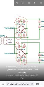
Re the ground lift, which diagram is correct or better, or are they just the same?
from @danieljw 's video here (thank you Daniel by the way, these videos have been so helpful, and I subscribed when you dropped the first one)
View attachment 1205852
or from the wolverine documents how to wire here
View attachment 1205853
I understand the top circuit has an additional RF filter installed parallel across the chassis ground and psu 0V line, however the top one has two sides of the bridge shorted and the other has only one side. Is one more "correct" or does it not matter due to the diodes in the bridge?
Try to draw the diodes in the bridge and you will see that the difference is in the voltage when the bridge opens and in the current load of the diodes
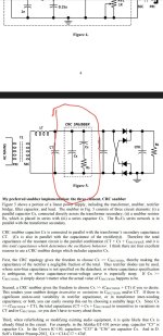
From what I understand the caps across the diode bridge is sort of an old practice. The caps were added to help a dampen the ringing from the primary winding as the diodes in the bridge suddenly switch off.
I believe this practice has been replaced by a cap in parallel and a zobel network across secondary winding.
(CRC Snubber)
Please refer to this thread for more details.
https://www.diyaudio.com/community/...-using-quasimodo-test-jig.243100/post-3645210
I believe this practice has been replaced by a cap in parallel and a zobel network across secondary winding.
(CRC Snubber)
Please refer to this thread for more details.
https://www.diyaudio.com/community/...-using-quasimodo-test-jig.243100/post-3645210
Attachments
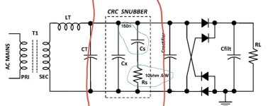
I understand how to measure with the Quasimodo V4 board but how would I determine the voltage rating of CT, CX, CS and the wattage rating rating for RS to use across say a 40-0-40 400VA toroid?
Nice product, going to try and order one.
Nice product, going to try and order one.
I believe page 7 all those details.
These are the parts I use
CS = 871-B32521C3154K289
CX = 871-B32521E6103K
RS = 0.5W resistor
These are the parts I use
CS = 871-B32521C3154K289
CX = 871-B32521E6103K
RS = 0.5W resistor
So to be clear... the snubber components need to be located as close to the transformer as possible, got it...
RS lets say I have to use a 10ohm resistor along with CS = 150n @ 160vac rating. The 10 ohm resistor can be a 1/2 watt? or does RS have to be around 5 0r 10 watts?
RS lets say I have to use a 10ohm resistor along with CS = 150n @ 160vac rating. The 10 ohm resistor can be a 1/2 watt? or does RS have to be around 5 0r 10 watts?
Attachments
The answer(s) are in the excellent treatise that MJ has written about the construction of the Quasimodo in the link Stuart referred to above (page 7):

Of course, you can use a 5W part, nothing bad will happen, but it will be a pretty big resistor and the leads may not fit the pcb itself. The amount of power dissipated is small, even with 10 ohms. 1 watt is fine as well.
I recommend reading MJ’s document at your leisure. For most it will be over their heads, however, you will learn something new on every read and jotting notes on a sheet of paper.
Best,
Anand.
Wanted to share my recent repair that my Wolverine required, in case it helps someone in the future. FYI - my setup PC, USB to Outlaw 975 single-ended to the Wolverine, running +/-68Vdc on EF4-3 boards from GB1, tested to provide 200/320 (8r/4r-both channels) and 225/350 (8r/4r-single channel). take these with a grain of salt, as I only ran the 4r tests for <30 secs only have 400w resistor bank (got hot, fast). Needless to say - way more than enough power and had I not already bought the Xfrmr, I would have gone closer to 60Vdc.
All started this past Monday mooring - turned the amp on as I do every morning, prepping for work meeting (WFH). The amp was idling and after ~30-mins, heard the dreaded "crackle-pop-fizzle" and "click" of the speaker protection. Went over and turned off the amplifier and thought Hmmmm, but I had to work, so I didn't get a chance to give it a good once over until that evening. First step, try and see what happened and take measurements - hooked up the DBT and turn on, no bright bulb, but the right channel had ~1.5Vdc, so that's why the protection tripped.
Disassembled the amp channel from the chassis for some sleuthing. Put it on the bench and powered up with 60w DBT and +/-65Vdc bench supply and the ~1.5Vdc quickly went to ~23Vdc and resistor (R111a) started smoking. So I tacked in a replacement 100r resistor, and changed to a 40w bulb in DBT. Turned on again to try and get some voltages and the DBT no longer lit-up outside the normal flash and go-out sequence, but I now had ~42Vdc on the output and that 100r R111a literally went up in smoke almost instantly. Time to do some poking around without power.
Carnage I found on Amp board - 5 of the 6 outputs (MJL4302/4281) were shorted, all the emitter resistors (12x0.47r 3W MOX) were high resistance, R116 (2.2r) and R111a (100r) were all high value. Disassembled more, separating the input/output boards and replaced all the burned, or out-of-spec parts on the amplifier board. Fairly confident I found all the issues on the amp board I turned to the input board.
Input board testing - first thing I noticed was that the CCS LEDs (D3, D12) were not lightning up, but tested fine in circuit. Proceeded to remove transistors that were testing odd in circuit, ended up testing all except for the LTP (Q1,Q2), Cascode (Q5,Q6), and Current Mirror (Q3,Q4) they all tested fine in circuit. Ended up pulling out 9 transistors, before I found the issue.
Carnage on Input Board - QHelp (A1845) had an Open junction (B-E IIRC). No other damage, so I changed that out and re-tested on the bench and now the LEDs lit and all input board tests passed.
Reassembled the boards and re-did the bench test with +/-65Vdc using 60w DBT and then 150wDBT - worked as it should, and everything adjusted perfectly. Let it idle for 30mins. just to be sure. Then reassembled the channel back into the chassis and did the initial set-up process on both channels (mainly checking the good channel, as it was working fine).
Unsure if the QHelp started the chain reaction, was it the result of running the power tests (unlikely as that was short time and let everything get back to idle temps before running another test), or a weak/faulty Output, R111a, or R128 that started the chain reaction. QHelp was not on my radar, because it passed the diode tests in circuit, didn't find the open junction until I pulled it out of the board.
Kudos to the team - blew 5 of 6 outputs, QHelp and a couple resistors, that tells me this is a well designed amplifier to have a catastrophic event and the damage was confined to a few components.
Moral of this long story - don't forget to test QHelp out of circuit and don't be like me and wait until you have already pulled out and tested 8 other transistors (maybe start with QHelp if your LEDs D3 and D12 aren't lighting).
Check your driver transistors as well. By the way which ones were you using? A 4ohm non-reactive load should be easy for the amp. If Qhelp was bad it would definitely send the output towards one of the rails at DC.
Jeremy
Jeremy
I am using KSC3503/a1381 for drivers and I did test them and they still measured close to what I matched them at. The only thing I can think of is QHelp was failing and going towards open when I had 1-2Vdc on the output, but failed completely when I was bench testing to find the problem and pushed the output to the full negative rail.
Sorry, I'm confused - meant 2SC4793/A1837 are my drivers, and I pulled them out and checked them, for Vbe and Hfe and checked out fine.
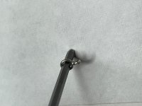
Offer/show my DIY solution $0.00 for test lead connection points (forgot to order and didn't want to pay $8 shipping for $3 in parts). I took the clipped emitter resistor leads (3w) and wrapped around a 2.5mm hex key, and twisted leads together with needle-nose pliers and soldered in position. Works great, and ended up only needing them for TP101 and TP102 (Bias), all other test points were easy to access during the build and testing process.
Attachments
I would be changing those drivers out +-68vdc is marginal at best for those depending on your load.
I think my speakers are a fairly easy load at 6.8r nominal, 2-way speaker and it's in a small office (10'x12'), so 80% of the time I'm only pushing 1-2 watts while I'm working, but I do stretch their legs once a week or so.
I have some MJE15032/33 from an old parts order but to save some money I didn't order R20, C4 or C5 - but should have leftovers for R20 from R1, R9 (390r), but will need to order C4 and C5. I will include these in my Mouser order in a week or so, planning to build a new daughter board for the M2x and try that out.
Thanks for the suggestion, really been enjoying this amp, so I should make it as bullet-proof as possible.
Sorry to hear of your amp burning , did your protection circuit have over-current sense ?Thanks for the suggestion, really been enjoying this amp, so I should make it as bullet-proof as possible.
I'm not "gloating' over a failure , but I find any failure very interesting - to make the next generation "bullet proof".
Edit - 2SC4793/A1837 are "wimpy" for over 2 pair outputs.
OS
I have followed this thread with great interest and is close to push the purchase-button.
However - I got these old builds of class D monoblocks with linear power supply of 55VAC/77VDC.
I saw some suggestions to bring down the voltage level with series diodes, unwind some secondary turns and even add some winding in the transformer in "opposite" direction. None of these option is very appealing to me but might be the only way to use them with the Wolverine?
Is 77VDC a "hard stop" or can it be used with some modification of components?
Thanks
- Home
- Amplifiers
- Solid State
- DIY Class A/B Amp The "Wolverine" build thread