Thats pretty clean! Hope I can get the same. I will make the ground lift circuit I have a 35A BR spare here. Couple things - Did you have the cobra's heatsink/frame isolated from the chassis i.e mounted via nylon standoffs? (I ask because on the cobra the 0V is tied to its heatsink, whereas the hypex the heatsink is isolated from its 0V). And did you end up keeping/using the micro ripple eaters?This measurement is in Chassis with a Cobra S2 +-63v. This is with th 0v tied to the T-Ground PCB.
View attachment 1138726View attachment 1138725
Are you sure about that? All the cobra SMPS I have tested the 0V is isolated from the heatsink. I didnt end up using the MRE's in my final builds but I do on my bench test setup. Just the ground lift and T-Ground.

OK good, because you want the heatsink tied to chassis ground for safety. If you have space for the MRE I would recommend installing, and then even a couple of 20,000uF caps per rail after it.
Received the email back, really appreciate it!
I’m sure that has been asked before, so my apologies. How does this amp (EF3-4) compare to the Honey Badger. I was considering buying that board as well, but if folks are like “don’t bother if you’re building the Wolverine” then I won’t.
Dan
I’m sure that has been asked before, so my apologies. How does this amp (EF3-4) compare to the Honey Badger. I was considering buying that board as well, but if folks are like “don’t bother if you’re building the Wolverine” then I won’t.
Dan
Dont bother if you are building the Wolverine. There I said it first 🤣
Dont bother if you are building the Wolverine. There I said it first 🤣
Lol, thank you. Is it a superior amp then? I
See you liked the post above danieljw, I’ve been watching all of your YouTube videos on the amp, thank you.
Dan
My packed arrived safely with the EF3-4 boards and all the goodies included.
A big thanks to the W-team for this design, bords looks amazing and definitely there's been thrown some hours into the project! Looking at the PCB's there really isn't a corner left that hasn't been thought of by the looks of it.
-Also a big thanks to @fireanimal for supplying me with some "hard to find" transistors for this build. Very much appreciated, I never thought that I would see MT-200's on my workbench 🙂
I'll have a couple of questions regarding parts selecting according to the boom. I'm not gonna deviate to much from the standard parts listed, but there will be some questions along the way before ordering.
I'll aske later when planing the final steps 🙂
Anyway, a big thanks 🙏 This is gonna be a fun project!
Best regards // K.Nielsen
I have both the Honey Badger and a couple Wolverines, all being used in my system right now. Stereo Honey badger from 200Hz and below, Twin mono Wolverines from 200Hz up. Both are very good amps. I can't hear a difference, but the Wolverine measures better and is a more advanced design.Lol, thank you. Is it a superior amp then? I
See you liked the post above danieljw, I’ve been watching all of your YouTube videos on the amp, thank you.
Dan
I re-ran this first stage test with a +-57vdc power supply and all readings were spot on according to the build guide.I'm using a +-24dc 2amp power supply, Fluke digital dual trace O-Scope and a Fluke 87 multimeter. I'm also using the TTC/TTA semi's.
My measurements;
A. TP107 and TP108: Board one,(B1) 493mv and Board two,(B2) 458mv.
E. R11 adjusts for 5.008 vdc on both boards
F. TP-3 and TP-4: 0.594 vdc on both boards
G. TP-105: (B1)1.29 and (B2) 1.27 vdc
TP-106: (B1)1.28 and (B2) 1.26 vdc
H. DC offset is (B1) 29mv and (B2) 22.5mv and that's all the adjustment I can get.
Switch to measure AC (B1) 1.3mv and (B2) 0.2mv. Are you guys sure these can get down to less than 0.080mv? That's less than 0.00008 volts ac! Is this a typo.. Should it say less than 80mv or 0.080 vac?
I. Bias adjusts to 1.42vdc on both boards.
One other thing I saw... Step E. TP-1 (DMM +) and TP-2 (DMM +) Should one of these be a negative.
If you all say it's all good, I'll press on to the next stage of testing.
Scott
Now to the chassis and large heatsinks.
Scott
In combination with the Cobra 2, has anyone tried this one: https://micro-audio.com/store/product/extra-capacitors-pcb-fully-populated/
It looks like a coil at V-in and that makes me wonder if this works as a LP-filter to sort out some of the HF switching noise from the SMPS?
I can't find a datasheet for the one in the link
Regards
It looks like a coil at V-in and that makes me wonder if this works as a LP-filter to sort out some of the HF switching noise from the SMPS?
I can't find a datasheet for the one in the link
Regards
I have but not with the Cobra. The cobra straight to the amp works without issue, even better is hifisonix MRE.
https://hifisonix.com/shop/hifisonix-micro-ripple-eater-mre-pcb/
https://hifisonix.com/shop/hifisonix-micro-ripple-eater-mre-pcb/
Yep Scott same here, I used variac on a jank old LPS I put together with the old transformer out of my chassis from 0vdc all the way up to 70vdc. Initially I tested at 20VDC then 30VDC. I think around 45VDC everything kind of fell into place and I got all correct readings, along with d10 and d11 finally lighting up at this voltage.I re-ran this first stage test with a +-57vdc power supply and all readings were spot on according to the build guide.
Now to the chassis and large heatsinks.
Scott
Stuart had some ideas but I’ll leave it up to him to comment if he chooses.
Thanks. I've looked at the MRE for month now. Only downside is a small Vdrop with one MRE pr channel, but I might just add them to the basket later on..I have but not with the Cobra. The cobra straight to the amp works without issue, even better is hifisonix MRE.
https://hifisonix.com/shop/hifisonix-micro-ripple-eater-mre-pcb/
Normally I've spent lots of energy filtering within the audioband with a linier PSU to eliminate artifacts where the SMPS is switching HF.. it's the last comment I find appealing.
Regards
Yes there is a slight voltage loss, to be honest you wont notice a difference with the cobra straight to the Wolverine. Just be sure to use a T-Ground and tie the 0V output to ground there.
I plan on going straight from Cobra to Wolverine, myself (including Stuart's T-ground/lift).
From @fireanimal observations and testing, I can't imagine I'd be able to notice the extremely low levels of ripple currents present on the outputs of the Cobra... on top of the relatively high amount of the amp's PSRR.
Just my assumption anyhow... I wish I had time to build right now. Can't wait to tackle this project.
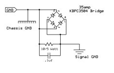
Re the ground lift, which diagram is correct or better, or are they just the same?
from @danieljw 's video here (thank you Daniel by the way, these videos have been so helpful, and I subscribed when you dropped the first one)

or from the wolverine documents how to wire here

I understand the top circuit has an additional RF filter installed parallel across the chassis ground and psu 0V line, however the top one has two sides of the bridge shorted and the other has only one side. Is one more "correct" or does it not matter due to the diodes in the bridge?
from @danieljw 's video here (thank you Daniel by the way, these videos have been so helpful, and I subscribed when you dropped the first one)
or from the wolverine documents how to wire here
I understand the top circuit has an additional RF filter installed parallel across the chassis ground and psu 0V line, however the top one has two sides of the bridge shorted and the other has only one side. Is one more "correct" or does it not matter due to the diodes in the bridge?
I read an article from https://www.tnt-audio.com/clinica/ssps1_e.html
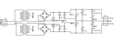
Is it worth adding C1,2,3,4,5,6,7,8 and R1,2?
Any thoughts before I start...
Thanks all.
Is it worth adding C1,2,3,4,5,6,7,8 and R1,2?
Any thoughts before I start...
Thanks all.
Attachments
- Home
- Amplifiers
- Solid State
- DIY Class A/B Amp The "Wolverine" build thread