I see it's all described in details in the BOM. Fantastic 😊

So since R109 was changed from 200 ohm to 500 ohm trimmer, I assume the correct set up procedure is still to set pins 1 and 2 to max resistance when installing i.e. to 500ohm, rather than 200 ohm the build guide (v34) mentions, in multiple areas?
The newest build guide (v35) mentiones R109 set to maximum value @500ohm 👍
500 Ohm is the recommended value.
With 200 Ohms after the modification you may have a small amount of bias
With the potentiometer at maximum and possibly not enough adjustment range.
A large amount of credit goes to Andy (fireanimal) since he did alot of actual testing post simulation (by Stuartmp and JJS) to make sure this potentiometer value was suitable.
- Also spend the couple of dollars for a Bourns 3296 potentiometer not a fake.
Hope this helps.
- Daniel
With outputcaps in my preamp, is it possible to bypass C1 without to much fuzz in the amplifier? Making the amplifier signalpath capfree...C1 is the only cap in the signal path on the wolverine. It measured the same as the film cap so therefore it will sound the same, I measured to give builders options / lower price alternatives if on a budget. Personally Film is the only way to go in that position, but to each their own.
Regards
I would say it is better not to do that for a few reasons.
Even though there is an output cap some preamps have a dc offset as the preamp powers up.
If you use another source it may have a dc offset
The capacitors recommended were chosen carefully not to impact the LF response and have been proven to have low THD.
I hope this is useful
- Dan
Even though there is an output cap some preamps have a dc offset as the preamp powers up.
If you use another source it may have a dc offset
The capacitors recommended were chosen carefully not to impact the LF response and have been proven to have low THD.
I hope this is useful
- Dan

With two transformers I would still try to stag them if possible with the ability to refuse some noise and keed the e.caps and bridges as one unit in one end og the amp.
If you wanna proceed with the internal mounted heatsink, good wiring needs quite some attention, as it's quite easy to make messy and big loops as previous mentioned in this thread..
My English is not the best, so hope there is not to many mistakes in my typo🙂
If you wanna proceed with the internal mounted heatsink, good wiring needs quite some attention, as it's quite easy to make messy and big loops as previous mentioned in this thread..
My English is not the best, so hope there is not to many mistakes in my typo🙂
Last edited:
@90scaraudio Could this be an option for further improvement in your layout? 🙂
Haven't drawn the signal/speaker-out wirring.
Blue is AC, yellow is wire from transformers and PSU. Green is the boards


The one where the heatsinks are close together, seems to be good at conducting heat, Chimney effect sort of.. But the transformers would be closer to one PCB then the other as a sideeffekt, but with some distance to the IPS...
Regards
Haven't drawn the signal/speaker-out wirring.
Blue is AC, yellow is wire from transformers and PSU. Green is the boards
The one where the heatsinks are close together, seems to be good at conducting heat, Chimney effect sort of.. But the transformers would be closer to one PCB then the other as a sideeffekt, but with some distance to the IPS...
Regards
Last edited:
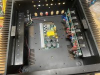
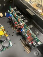
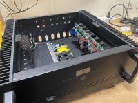
Dummying up how its going to sit, sure looks lost in the old parasound 6 channel chassis. Nearly ready for testing. Boards also still need final clean.
Attachments
Yes, there will be once our current stock runs out. We still have a few boards available. If you send me your order sheet I'll get your order underway. You can find instructions on how to order in the first post of the Wolverine build thread.Will there be another group buy at some point for these wolverine boards ?
Hi Guys,
I have updated the Build Guide, Current revision is now 36.
Revisions noted as the end of the document.
I have updated the Build Guide, Current revision is now 36.
Revisions noted as the end of the document.
You can do this but you need to drive one amp with an inverted input, and each amp sees a lower impedance.Can you bridge two EF3-4 boards together for a higher output? ie 2 boards in each monoblock?
What are you planning to drive with it ?
Looks like a very interesting amplifier to build. Haven't read the whole thread (yet) but have tried to search for answers on some questions I have;
1) What are the audible differences between a lineair and SMPS power supply?
2) How much idle power does the Wolverine use?
3) How difficult would a three or four channel amplifier be to build? (I need at least three per speaker)
1) What are the audible differences between a lineair and SMPS power supply?
2) How much idle power does the Wolverine use?
3) How difficult would a three or four channel amplifier be to build? (I need at least three per speaker)
- Home
- Amplifiers
- Solid State
- DIY Class A/B Amp The "Wolverine" build thread