Question for the designers. I replaced the capacitors, resistors in the cap multiplier and replaced the two resistors with diodes on the rails. Will this change the bias? I'm suspecting, slightly because the rail voltages will probably slightly change.

Yes, just slightly. A small adjustment might be necessaryQuestion for the designers. I replaced the capacitors, resistors in the cap multiplier and replaced the two resistors with diodes on the rails. Will this change the bias? I'm suspecting, slightly because the rail voltages will probably slightly change.
Jeremy
Just FYI for everyone else, bias changed very little, if at all. The 5V CSS1 changed a couple tenths of a volt.
With help from Stuartmp, I have reconfigured the parts in my mono block Wolverine to minimize loop interactions. Here is the result.

Looks great Richard. Can't wait to hear your thoughts on how it sounds once your complete.With help from Stuartmp, I have reconfigured the parts in my mono block Wolverine to minimize loop interactions. Here is the result.
View attachment 1112847
Last edited:

Well, I forgot to change the feedback path, had the snubber capacitors in the wrong positions and forgot to add a film capacitor at the output of the power supply board. Jees, now I think it is done and the other is half way there.Looks great Richard. Can't wait to hear your thoughts on how it sounds once your complete.
Hi Guy's
I just posted a small update to the BOM.
1. The 14 Pin SIP 1 header is now the preferred size as 10mm stand offs are easier to source.
2. The allowable rail voltage for the TTA004 and TTC004 transistors have been increased to 70V.
A big thanks to @Harry3 for keeping the BOM so neat and up to date.
I just posted a small update to the BOM.
1. The 14 Pin SIP 1 header is now the preferred size as 10mm stand offs are easier to source.
2. The allowable rail voltage for the TTA004 and TTC004 transistors have been increased to 70V.
A big thanks to @Harry3 for keeping the BOM so neat and up to date.
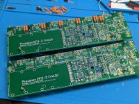
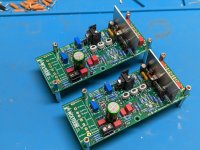
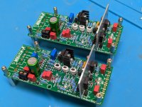
Currently building a pair of EF3-3 boards from the 2nd group buy. These will be using MJL4281/MJL4302 Outputs on 70v rails. As with the first group buy, these boards are excellent to solder and work with!!
Attachments
@fireanimal
Beautiful pics, thanks for posting. I just got my EF3-4 boards (in blue) and they are indeed very well made! I’ll see what I can come up with regards to the heat spreaders but if I don’t like them, I’ll hit you up!
Best,
Anand.
Beautiful pics, thanks for posting. I just got my EF3-4 boards (in blue) and they are indeed very well made! I’ll see what I can come up with regards to the heat spreaders but if I don’t like them, I’ll hit you up!
Best,
Anand.
Everyone,
Regarding the use of copper/aluminum plate to spread the heat across two 200mm long (for 400mm deep chassis). You don't need to use a heatspreader as long the output transistor are evenly spread out across the two heatsinks like the Wolverine/EF3-4 design. Some designs have all the outputs located on one of the 200mm sections rendering the other 200mm section useless. In that situation a heatspreader would help.
Jeremy
Hi Guy's,
I have made a small update to the build guide. It relates to the EF3-3 boards. Check the revisions for further details.
I have made a small update to the build guide. It relates to the EF3-3 boards. Check the revisions for further details.
Hi Guy's
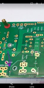
Just a heads up for all EF3-4 2nd Group buy builders.
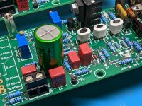
There is an extra solder link to solder on the feedback trace. See attached photo.
Is location was left over from the 1st Group Buy boards and should have been removed.
It was removed on the 2nd GB EF3-3 boards, but I missed it on the EF3-4 boards.
Please don't forget to solder this solder link.
I'm in the process of building my own set of EF3-4 boards at the moment and am tweaking the build guide as I go.
Just a heads up for all EF3-4 2nd Group buy builders.
There is an extra solder link to solder on the feedback trace. See attached photo.
Is location was left over from the 1st Group Buy boards and should have been removed.
It was removed on the 2nd GB EF3-3 boards, but I missed it on the EF3-4 boards.
Please don't forget to solder this solder link.
I'm in the process of building my own set of EF3-4 boards at the moment and am tweaking the build guide as I go.
Attachments
Hi everyone, finally finished my extreme build version.
72Vdc rails, 2000va transformer with 4 secondaries for duel mono PSU arrangement.
4 big 68000uF caps per channel.
My own slow start and a DC blocker just before the transformer also.
Thanks to Stuart Penberthy and Daniel Wiering the build has gone smooth and trouble free.
I also welded up my own internal shields that act as second level shelves for holding my slow start, DC blocker and rectifiers.
I used the Quasimodo V4 to make filters for all 4 secondary windings on the transformer also.
I have achieved 48.5Vrms into 8 Ohm, and 45Vrms into 4 Ohm output in my testing.
45Vrms out into 4 Ohm made my rail voltage sag from 72Vdc to 68.5Vdc.
Nice build. I wonder how critical transformer snubber is to wolverine?
I like how you stacked everything. I don't have access to metalworking tools so the only option is to use 3d printed analog. Abs plastic in theory remain stable for temps up to 100 c.
I like how you stacked everything. I don't have access to metalworking tools so the only option is to use 3d printed analog. Abs plastic in theory remain stable for temps up to 100 c.
I could see the difference it made to the ringing in the transformer, so in an all out build I added it as a just in case.Nice build. I wonder how critical transformer snubber is to wolverine?
I like how you stacked everything. I don't have access to metalworking tools so the only option is to use 3d printed analog. Abs plastic in theory remain stable for temps up to 100 c.
Not sure how much difference it makes in the real life circuit itself.
It's not mandatory, but a nice addition.
I designed my own Quasimodo V4 board and Rectifier filter boards also
@Garethllywelyn
What a nice and inspiring build, thanks for sharing. Are the gerbers for those rectifier pcb's availlable?
What a nice and inspiring build, thanks for sharing. Are the gerbers for those rectifier pcb's availlable?
Currently using Tidal on a PC and an SMSL Sanskrit pro DAC, with my own custom made Cascode BOZ preamp.Nice work! What is it mated with and how does it sound?
Regards.
And running with my Three way traditional floor standing speakers using fountek ribbons, and SB acoustic drivers.
The sound, it's still coloured by the front end at the moment, not had a chance to test with a zero harmonic front end yet.
But the sound is very detailed and fast, very good sound stage, and the Bass is the most controlled and detailed I've ever heard out of these speakers.
Very different to the sound off my normal class A amps, which are tuned to sound like valve amps.
But the wolverine is amazing in its own, absolute clean perfection performance way.
A nice thing to do on a dark winter day: cutting keratherm insulators. I realised that Keratherm is locally distributed through Conrad Elektronik in Germany. I got myself a sheet of 86/82, 190mm X 190mm in 0,25mm thickness.
The pads sold in the diyaudio store are quite big to fit for TO 247 case, but as I will use TO3-P devices I choose to cut pieces of 21mm x 27mm. That adds up to 7x9 = 63 insulators (and no waste) from my sheet. should be enough for the next few projects..


The pads sold in the diyaudio store are quite big to fit for TO 247 case, but as I will use TO3-P devices I choose to cut pieces of 21mm x 27mm. That adds up to 7x9 = 63 insulators (and no waste) from my sheet. should be enough for the next few projects..
- Home
- Amplifiers
- Solid State
- DIY Class A/B Amp The "Wolverine" build thread