Thanks!You are truly an animal! Great progress !
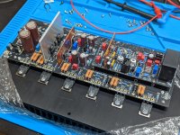
So all 6 boards passed testing with no output transistors. Now on to the next step. 😎
Attachments

Well Done ! Keep going !Thanks!
So all 6 boards passed testing with no output transistors. Now on to the next step. 😎
I showed my wife your photo of 6 boards to let her know how lucky she is that I am only building 2. Her response "he must be single....and don't get any ideas!"6 Channels complete and ready for testing! Man that was A LOT of soldering!!!
I showed my wife your photo of 6 boards to let her know how lucky she is that I am only building 2. Her response "he must be single....and don't get any ideas!"
LOL!!!
Imagine that I couldn't show her even 1 board!!! I'll bring the new amp, once done, at home when she is out. Like a secret agent...
LMAO!! Yes this is why I go overboard, to make it easier on the rest of you!! Just kidding, I am not single, just lucky I guess.I showed my wife your photo of 6 boards to let her know how lucky she is that I am only building 2. Her response "he must be single....and don't get any ideas!"
On that note, mailman came with more nice things for me! 😍

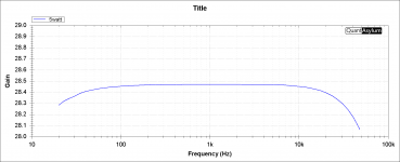
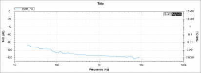
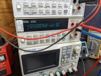
So here are measurements of my first completed board.
WOW!!!!!!!!!!!!!!!
DC offset - basically 0 and stable
WOW!!!!!!!!!!!!!!!
DC offset - basically 0 and stable
Attachments
From experience you don't want the fan that close. There will be alot of higher frequency noise coming from the motor.If anyone's wondering what the updated matcher looks like, here it is.
Wow, that's amazing. Can I pinch that image and add it to the front of the build guide?6 Channels complete and ready for testing! Man that was A LOT of soldering!!!
Sure!Wow, that's amazing. Can I pinch that image and add it to the front of the build guide?
Nice base measurements. Similar to what I got without a distortion magnifier.So here are measurements of my first completed board.
WOW!!!!!!!!!!!!!!!
DC offset - basically 0 and stable
You will need a distortion magnifier to measure the actual distortion as is lower that the loopback distortion of the QA-40X
See this album for the wiring layout.
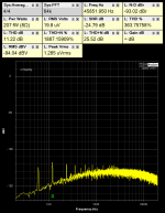
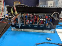
I can't stress enough how important the cables, connectors, load resistor are at this level. Pay close attention to the connections and the actual layout of the wires if you want to measure this optimally.
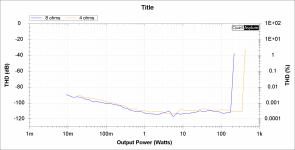
I measured 0.0000204% at 1khz into 8 ohms, 80wrms using the arrangement shown.
Distortion setup
The amplifier shown was prototype 2
Yes that was my impression too. The amplifier is better then the analyzer! I was impressed how the 4 and 8 ohm track each other right to clipping as well as how low the distortion stays at high frequencies. Absolutely amazing! All you guys did an unbelievable job on this project start to finish! Thanks again for all the time and effort on this design! 🍻👍🏻
From experience you don't want the fan that close. There will be alot of higher frequency noise coming from the motor.
Thanks, I'm in the middle of updating the placement of the boards and will take this into consideration
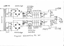
Hi Janusz,Attached is proposed Wolverine PS for my EF3. It's based on my Honey Badger PS but somewhat upgraded. Appreciate any comments.
cheers,
It looks like a reasonable power supply but the 3k3 bleeder resistors may need a higher power rating, 5W is probably better.
One alternative is to use a higher resistance value (4k7 5W) or similar value in series (3k3 2W x2) I only mention this because they will run very hot with 72V rails/3300 Ohm.
I hope this is helpful.
What sort of VA rating are you planning to use ?
- Daniel
The team is concerned that the SOA of the output transistors might be exceeded if builders use high voltage, regulated power supplies into 4R loads i.e. Switch mode power supplies or very large VA transformers that don’t allow the voltage to sag.
Jeremy has done the simulations and I have added additional information on Sheet 2 of the BOM (in blue). This should help you decide on the maximum voltage you can use for each output transistor type.
This is a necessary precaution, so builders do not blow up their amps when using them under hard conditions.
For “normal” linear power supplies there are no changes.
Unfortunately we did not update the driver voltages. I will upload the corrected BOM soon. Sorry.
Thanks for your efforts on this topic guys it is appreciatedUnfortunately we did not update the driver voltages. I will upload the corrected BOM soon. Sorry.
- Daniel
Yes, you are right. I'll probably use two 10k resistors in parallel like in my HB or one 4k7 5W. Thanks,Hi Janusz,
It looks like a reasonable power supply but the 3k3 bleeder resistors may need a higher power rating, 5W is probably better.
One alternative is to use a higher resistance value (4k7 5W) or similar value in series (3k3 2W x2) I only mention this because they will run very hot with 72V rails/3300 Ohm.
I hope this is helpful.
What sort of VA rating are you planning to use ?
- Daniel
- Home
- Amplifiers
- Solid State
- DIY Class A/B Amp The "Wolverine" build thread