Thanks Daniel, I know how much time and effort has gone into producing these videos.Hi Everyone,
I have a new video up on the completion of the main board:
Enjoy!
-Dan
I hope that your videos are watch by all who build this amplifier as they are a valuable addition to the build guide.
If you guy's enjoy Daniel's videos please take the time to leave a comment. I'm sure that he'll appreciate your feedback.


can someone mention the resistor and capacitor reference locations that fall within the signal path. And toshiba, sanken and onsemi output transistors sounds different in the board?
Some testing info on Matcher; start at post 203:
https://www.diyaudio.com/community/...uring-the-results.307138/page-11#post-6209909
https://www.diyaudio.com/community/...uring-the-results.307138/page-11#post-6209909
Per Anatech, with regard to Matcher schematic,
Caps in parallel to collecter/base resistors are not required
C7 thru C10 and C3 thru C6
Caps in parallel to collecter/base resistors are not required
C7 thru C10 and C3 thru C6
Does anyone know if I wound the output coils backwards here? urgh fail.
Attachments

Last edited:
It looks like it but it will still work just the same.Does anyone know if I wound the output coils backwards here? urgh fail.
Jeremy
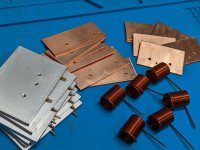
Spent today making all the heatsinks and winding coils. I remade the CCS/VAS heatsinks because I wasn't happy with the 1st ones. On a side note the pins for the driver heatsink are a tight fit, I had to use my drill press as a press to push them in, but that's a good thing as they will have excellent contact in the heatsink!
Attachments
Per Anatech, with regard to Matcher schematic,
Caps in parallel to collecter/base resistors are not required
C7 thru C10 and C3 thru C6
Hi Greg, please what do you mean C7 thru C10 and C3 thru C6? Could I get rid of these caps?
Thanks,
Gaetano.
These are shoulder washers, also known as step washers. McMaster-Carr has a very good selection of them.I have been trying to find a way to reliably isolate metal screws and spacers from pcb tracks on both the input and main pcb's. Ended up using those TO126 plastic mounting washers and slightly adjusting my spacer length. I have a collection of those washers so not sure where to buy. Perhaps this will help if you are stuck.
Clockwise is correct as noted in the BomDoes anyone know if I wound the output coils backwards here? urgh fail.
I am left handed and anti-clock is the only way I can wind the damn things tightly, but as @jjs notes, the inductance does not care.Does anyone know if I wound the output coils backwards here? urgh fail.
Maybe a close photo of the coil would help.
The reason I say clockwise is because the holes in the pcb are offset from the centreline of the inductor. Winding the inductor coil clockwise will enable it to fit easier.
The other holes in the PCB on the centreline of the inductor are if people want to run their zobel resistor through the centre of the inductor above or below the PCB.
The other holes in the PCB on the centreline of the inductor are if people want to run their zobel resistor through the centre of the inductor above or below the PCB.
I am left handed and anti-clock is the only way I can wind the damn things tightly, but as @jjs notes, the inductance does not care
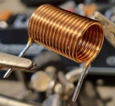
Here is mine I just started, letting glue set before I make them the correct size tonight.Here is a couple of photos of mine if it helps
Clockwise wound
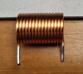
Installation of my output coil,
1.3mm wire.
Used mobile phone style clear glue for the inside to hold it together.
PCB standoffs and nuts etc are temporary until proper bolts and bits arrive.
Waiting on some transistors before I finish the board.
My 14 turn coil turned out well I think


1.3mm wire.
Used mobile phone style clear glue for the inside to hold it together.
PCB standoffs and nuts etc are temporary until proper bolts and bits arrive.
Waiting on some transistors before I finish the board.
My 14 turn coil turned out well I think
Yes that is correctHi Greg, please what do you mean C7 thru C10 and C3 thru C6? Could I get rid of these caps?
Thanks,
Gaetano.
- Home
- Amplifiers
- Solid State
- DIY Class A/B Amp The "Wolverine" build thread