

You will not get 72.5V out, but you probably know that.Attached is proposed Wolverine PS for my EF3. It's based on my Honey Badger PS but somewhat upgraded. Appreciate any comments.
cheers,
I have uploaded the new BOM with additional information on Sheet 2, written in blue.
I purchased a pair and received yesterday, they fit the ef3-3 perfect, no adjustment required, thanks ZachView attachment 1059805
If anyone in the US is having trouble sourcing or making the inductor, I’m willing to make extra epoxy dipped coils for $10 shipped per pair. Pm if interested, I probably have enough wire for a dozen coils.
Couple things, If anyone is looking for proper depth Standoffs for the UMS heatsinks so you don't have to cut them down here is the digikey P/N - 1772-1902-ND.
Also I just ran into a very strange issue while biasing another board. The bias would respond very slowly to the POT, then it would raise to maybe 20 mV then jump right up to 150 mV. I was trying to figure if I had a bad pot, or transistor, but I remembered that during the precheck step, I had no issues with the bias adjusting normally from the drivers. I had 3 meters connected monitoring bias, DC offset and the 5V. For some reason my meter was putting noise or feedback on the resistor for TP1/TP2 and once I disconnected it then I was able to bias with no problem. The really strange part is I switched the meter leads around and no problems....
Also I just ran into a very strange issue while biasing another board. The bias would respond very slowly to the POT, then it would raise to maybe 20 mV then jump right up to 150 mV. I was trying to figure if I had a bad pot, or transistor, but I remembered that during the precheck step, I had no issues with the bias adjusting normally from the drivers. I had 3 meters connected monitoring bias, DC offset and the 5V. For some reason my meter was putting noise or feedback on the resistor for TP1/TP2 and once I disconnected it then I was able to bias with no problem. The really strange part is I switched the meter leads around and no problems....
That standoff is 10mm, the optimal standoff length is 8mm because this insures the there is enough lead protrusion of Q103 and Q104 (TO-126/TO-225) through the cicuit card when mounting the pcb parallel to the heatsink. I'm not sure how you are mounting your boards.Couple things, If anyone is looking for proper depth Standoffs for the UMS heatsinks so you don't have to cut them down here is the digikey P/N - 1772-1902-ND.
Also I just ran into a very strange issue while biasing another board. The bias would respond very slowly to the POT, then it would raise to maybe 20 mV then jump right up to 150 mV. I was trying to figure if I had a bad pot, or transistor, but I remembered that during the precheck step, I had no issues with the bias adjusting normally from the drivers. I had 3 meters connected monitoring bias, DC offset and the 5V. For some reason my meter was putting noise or feedback on the resistor for TP1/TP2 and once I disconnected it then I was able to bias with no problem. The really strange part is I switched the meter leads around and no problems....
Jeremy
Last edited:
Yes I had no issues with them on mine (EF3-3), but someone mentioned on the EF3-4 board that 10 mm height was too much, and 8mm was preferred.Th
That standoff is 10mm, the optimal standoff length is 8mm because this insures the there is enough lead protrusion of Q103 and Q104 (TO-126/TO-225) through the cicuit card when mounting the pcb parallel to the heatsink. I'm not sure how you are mounting your boards.
Jeremy
8mm P/N - 1772-1990-ND. Not sure why they are more money though
Standoffs are the sort of item that are better purchased through eBay or AliExpress than digikey or Mouser. For example, here is an advertisement for 50 units of 8mm M3 M-F standoffs with a delivered price of $5.60 (US): https://www.aliexpress.com/item/325...a16547106509351643e8bef!12000022714905858!sea. Hard to beat, in my opinion. Yes, delivery won't be overnight, but given the savings it's a great deal.
I agree cheaper the better, but sometimes waiting weeks/months from china wears on ones patience. I was only giving an option for those looking for correct thread depth for the UMS heatsink so they don't need trimmed to <5mm.
Hi Guy's,
I just made a few small updates to the build guide. Thank you to @fireanimal for his input. 🙂
The current version is now revision 20 (10-06-22)
Updates are noted at the end of the file.
I just made a few small updates to the build guide. Thank you to @fireanimal for his input. 🙂
The current version is now revision 20 (10-06-22)
Updates are noted at the end of the file.
Please see line 94 on sheet 1 of the spreadsheet for C115 and C117. Sheet 3 identifies suitable part numbers and their ripple current maximums for those capacitors for different rail voltages at high loads. Those capacitors need to have a low series resistance to avoid over heating with early failure during sustained high loads.@stuartmp what are the caps on sheet 3 of the latest BOM? For PSU? Thanks 👍
At normal domestic listening levels the ripple current requirements are unlikely to exceed most capacitor ratings but as a rule of thumb I prefer to buy the lowest affordable series resistance types.
Hope this helps
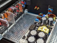
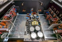
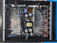
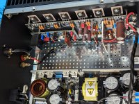
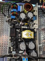
1st Chassis is now complete! I am testing the amp on my JBL Studio 590's and WOW does it sound awesome! The SMPS from Microaudio is top notch, comparing it to linear supplies I have built in the past, you would not know the difference, minus the weight and extra wiring. I do have a bit higher noise floor on the left hand board, but I am going to try some aluminum or copper plate to create a shield between the SMPS input and the left channel. I measured the left channel at -91 dbV A-weighted and the right channel at -94 dbV A-weighted, but its below what I can hear through my speakers.
Not sure how that compares with other builds, my wiring could also use a tweak, but I want to run this amp in over the next few days, then remeasure the voltages to see how stable it stays.
The final home for 2 of the amps / 4 channels is going to be for my JBL Project Array 1400's that are being actively crossed over with a Minidsp flex. After listening to this amp on my baby JBL's, I cannot wait to get another amp chassis complete!!
Thanks again to the TEAM for all the work on this amazing amp!
Attachments

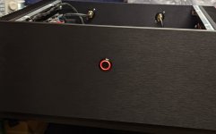
@fireanimal Do you have a source and part number for the power switch. That is exactly what I have been looking for.
Yep. Amazon. MGI SpeedWare Black Aluminum Push... https://www.amazon.ca/dp/B08FWWQC49?ref=ppx_pop_mob_ap_share
Just to update. The problem is with 1 of my meters that is for some reason causing the amp to oscillate. Neither of my other meters cause this to happen.Couple things, If anyone is looking for proper depth Standoffs for the UMS heatsinks so you don't have to cut them down here is the digikey P/N - 1772-1902-ND.
Also I just ran into a very strange issue while biasing another board. The bias would respond very slowly to the POT, then it would raise to maybe 20 mV then jump right up to 150 mV. I was trying to figure if I had a bad pot, or transistor, but I remembered that during the precheck step, I had no issues with the bias adjusting normally from the drivers. I had 3 meters connected monitoring bias, DC offset and the 5V. For some reason my meter was putting noise or feedback on the resistor for TP1/TP2 and once I disconnected it then I was able to bias with no problem. The really strange part is I switched the meter leads around and no problems....
If you are using linear power supplies with large transformer(s) and large filter caps you must use a soft start to “slow” down the current surge when turning on the mains power to the amp.
Also the mains switch needs to have a high current rating to survive the surge. Most of the vandal proof switches on the net are described as 3 - 5 Amps. There are however some that are rated at 10 Amps (if you believe the description). Generally speaking I would use the 10A (or more) type for large power amps.
See articles below that deal with this problem:
https://sound-au.com/project166.htm
https://www.diyaudio.com/community/...ains-relay-includes-soft-start-h9kpxg.354971/
https://www.diyaudio.com/community/...-pillow-sfp-ssr-soft-start-circuit-gb.350441/
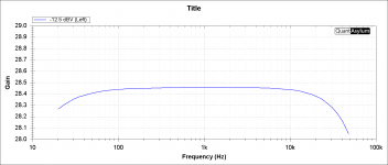
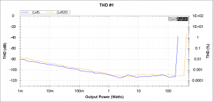
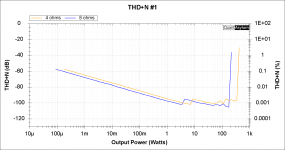
Novice here, & yes I realize an AVR is not the "cleanest" source, although I'd argue THD+N of 0.001 is clean enough;
What is the input impedance of the wolverine - will it be hampered by the (speculative) high output impedance of a Denon X3700H AVR @ around 1.2kohm?
And also the input sensitivity or gain figure - just to workout power output at say 1 to 1.5V input.
What is the input impedance of the wolverine - will it be hampered by the (speculative) high output impedance of a Denon X3700H AVR @ around 1.2kohm?
And also the input sensitivity or gain figure - just to workout power output at say 1 to 1.5V input.
- Home
- Amplifiers
- Solid State
- DIY Class A/B Amp The "Wolverine" build thread