
About to put in my last order, before I do wanted to see if anyone has matched outputs leftover from their build?
Otherwise I'll order whati need for MJE15034/5 and MJL4281 and MJL4302 as the price difference is relatively small between those and other options outside 2SC5200 and 2SA1943.
Thanks all!
Otherwise I'll order whati need for MJE15034/5 and MJL4281 and MJL4302 as the price difference is relatively small between those and other options outside 2SC5200 and 2SA1943.
Thanks all!
Which illustrates the need to measure. I will post some pictures of my completed amps and look for feedback on what is causing the 60Hz and odd harmonics of that. I'm not that worried about the final Harmonic Distortion on the amp itself, I am sure it is below what I can measure at this point.
Here is a picture of the wiring. Both amps are identical and measure practically identical. I have moved wires around while watching the spectrum analysis and I have seen nothing that has changed the problem with 60Hz and the odd order harmonics. Ideas?

Hi RickRay,
First off, well done so far, its great to see your build is progressing well.
I think you are close to a good result. I particularly like the use of the solid state protection board.
Please don't take the below as criticism because I can see you have put thought and care into your build, I am just going to give you some pointers:
I encourage you to read the ground loop document that Bonsai produced thoroughly, don't skip this step.
After reading the document, apply all of the suggestions to your amplifier build to the best of your ability.
A few of things I noticed immediately which may also help:
Twist you speaker wiring tightly and get it away from the centre of the toroidal transformer.
Run your speaker wiring tightly parallel to the heatsink in the steel bracket along the top or bottom edge, perhaps zip tie it or use small plastic brackets/clips. Neilshop's build has a great example of this. Keep a little clearance so your screws don't foul on the wire.
Do the same with your yellow and blue wires, they are forming a large loop area around the transformer, I would consider trying the yellow and blue wires on both sides of the case to determine which is the lowest noise option.
Do similar with your control / switch wires, they are forming a large loop area.
Consider using an audio ground lift, your mains ground stays solidly as you have it. (per Bonsai's document)
Use star washers on a couple of screws on each panel to ensure the anodising is cut through to ensure each and every panel is earthed solidly, without power connected check this with a digital multimeter at your nice Schurter power inlet module earth pin. Kudos for using a nice power inlet module.
If after all this you still have hum, try changing the orientation of your transformer output leads in 1/4 turn intervals (with the amp safely powered down when you work on it of course) Twist the toroid's primary and secondary leads tightly.
That is it for now.
It would be great if you could let us know if this reduces the noise on your FFT capture with the same settings.
Hope this helps
- Dan
I talked to Stuart tonight and he mentioned almost all the changes you suggest, but you have a couple very nice suggestions he didn't mention. I am moving most of the pieces around in the chassis after talking to Stuart. i'll share the mock-up picture on here when I do that, maybe it will help someone else.
I agree, hopefully, I'll be able to measure after correcting a lot of issues and see a nice improvement!
I agree, hopefully, I'll be able to measure after correcting a lot of issues and see a nice improvement!
looking forward to itI talked to Stuart tonight and he mentioned almost all the changes you suggest, but you have a couple very nice suggestions he didn't mention. I am moving most of the pieces around in the chassis after talking to Stuart. i'll share the mock-up picture on here when I do that, maybe it will help someone else.
I agree, hopefully, I'll be able to measure after correcting a lot of issues and see a nice improvement!
One knowledge from testing boards according to the Wolverine IPS & Precision EF3-3 Build Guide:
15. Initial Power up: 3 things to observe for “normal” behavior – point G.
I measured a voltage of 2.4V, it was caused by a voltage drop on the bulb installed instead of the fuse !!!
Maybe it would be interesting for the Wolverine team to get and publish the status of the amp builds from the builders (updated 1x per month). I have two IPS + EF3-3 boards tested without output transistors.
Hi @miran50 please download the latest version of the build guide. We are now at version 21One knowledge from testing boards according to the Wolverine IPS & Precision EF3-3 Build Guide:
15. Initial Power up: 3 things to observe for “normal” behavior – point G.
I measured a voltage of 2.4V, it was caused by a voltage drop on the bulb installed instead of the fuse !!!
Maybe it would be interesting for the Wolverine team to get and publish the status of the amp builds from the builders (updated 1x per month). I have two IPS + EF3-3 boards tested without output transistors.
Attachments
Nice work danieljw,eliminating the 50 Hz harmonics in measuring procedure is a very difficult job.
That doesn't mean really gnd loops in amplifier itself.
Make shure that you have power your p.c from a different socket than your amplifier under test.
Use a long power cord to connect one of this to a different room socket.
Test once and then reverse amplifier's power socket and test again.
That doesn't mean really gnd loops in amplifier itself.
Make shure that you have power your p.c from a different socket than your amplifier under test.
Use a long power cord to connect one of this to a different room socket.
Test once and then reverse amplifier's power socket and test again.
Hi Thimios,Nice work danieljw,eliminating the 50 Hz harmonics in measuring procedure is a very difficult job.
That doesn't mean really gnd loops in amplifier itself.
Make shure that you have power your p.c from a different socket than your amplifier under test.
Use a long power cord to connect one of this to a different room socket.
Test once and then reverse amplifier's power socket and test again.
That is a clever test you mentioned.
I have never tried that before
- Dan
The location of DMM1 in the schematic explains it, but the schematic is shown in point 20.Hi @miran50 please download the latest version of the build guide. We are now at version 21
@danieljw You used a harmonic amplifier to decrease your noise floor, that is one very nice piece of equipment. Question, would an active notch filter before the audio interface also allow you to decrease the noise floor? Not suggesting you do that. I don't want to invest in building a distortion amplifier for the amount of measurements I do, howerver I can buy a COSMOS APU for a very nice price that would give me +30dB at 1kHz and 10kHz.
Excellent video!!!! Double check if the noise figures are accurate while using coherent averaging, pretty sure they are not, that's why they are colored differently.
Excellent video!!!! Double check if the noise figures are accurate while using coherent averaging, pretty sure they are not, that's why they are colored differently.
Folks:
I could use some help with my Wolverine build. I'm at the testing stage and am getting similar unsatisfactory readings on both channels. Here is the latest background data:
Rail voltages are +/- 48.5 VDC
Jumper J103 is installed on both channels.
The inputs on both channels are shorted.
Pots R25, R11 and R109 were initially adjusted as instructed in the Build Guide.
0.5A slow blow fuses are installed.
The amplifiers' outputs are not shorted.
Q104 is installed but not mounted (it's hanging loose on both channels).
All six LEDs light (true for both channels).
I get the following readings:
Left channel
R111A to R111B = approx 810 mV
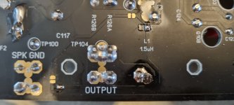
The maximum reading across TP1 and TP2 is 611 mV
TP3 to TP4 = 623 mV
TP5 to + terminal = 1.451 V
TP6 to - terminal = 1.485 V
Right channel
R111A to R111B = approx 819 mV
The maximum reading across TP1 and TP2 is 133 mV
TP3 to TP4 = 623 mV
TP5 to + terminal = 1.408 V
TP6 to - terminal = 1.438 V
Any and all guidance is appreciated!
Regards,
Scott
I could use some help with my Wolverine build. I'm at the testing stage and am getting similar unsatisfactory readings on both channels. Here is the latest background data:
Rail voltages are +/- 48.5 VDC
Jumper J103 is installed on both channels.
The inputs on both channels are shorted.
Pots R25, R11 and R109 were initially adjusted as instructed in the Build Guide.
0.5A slow blow fuses are installed.
The amplifiers' outputs are not shorted.
Q104 is installed but not mounted (it's hanging loose on both channels).
All six LEDs light (true for both channels).
I get the following readings:
Left channel
R111A to R111B = approx 810 mV
The maximum reading across TP1 and TP2 is 611 mV
TP3 to TP4 = 623 mV
TP5 to + terminal = 1.451 V
TP6 to - terminal = 1.485 V
Right channel
R111A to R111B = approx 819 mV
The maximum reading across TP1 and TP2 is 133 mV
TP3 to TP4 = 623 mV
TP5 to + terminal = 1.408 V
TP6 to - terminal = 1.438 V
Any and all guidance is appreciated!
Regards,
Scott
And you have tried adjusting the pot for CSS #1, right next to TP1 and TP2? Does the reading change any as the pot is turned from one extreme to the other? Also, NEVER short the outputs. R111A to R111B is normal, probably rising, when you put Q104 between your fingers it will go down, verifying the bias circuit is adjusting for heat. TP5 and TP 6 look normal also if using the TTC FET's.
I'll let the more knowledgeable guys help track down why your CSS's are not measuring right.
I'll let the more knowledgeable guys help track down why your CSS's are not measuring right.
RickRay:
Yes, the pot next to TP1 and TP2 is R11, and the best I could get from adjusting it was 611 mV (L ch) and 133 mV (R ch). And yes, I'm using the TTA and TTC FETs. The readings across R111A and R111B started out lower (about 780-790 mV) and slowly rose, settling at 810 mV (L ch) and 819 mV (R ch).
Regards.
Your meter is connected to both TP1 and TP 2 correct. If so, it is beyond what I can help with.
Pretty sure there is a schematic in the build guide that has voltages annotated on it. The 50 volt one should be in the ballpark.
- Home
- Amplifiers
- Solid State
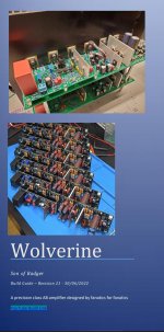
- DIY Class A/B Amp The "Wolverine" build thread