Yes you can, I use the 594-MBB02070Z0000ZCT myself, and the world is still turning.Hi Guys, two questions:
Can I use this 0.6watt 0 ohm resistor as J101 and J102?: 594-MBB02070Z0000ZC1

It seems like there might be a demand for a simpler version of the Wolverine that retains it's essence but looses some of the complexity and cost...
https://www.diyaudio.com/community/...lverine-and-cordell-book.400341/#post-7378116
https://www.diyaudio.com/community/...smd-60w-amps-wolverine-compatible-ips.398785/
Just an observation in case somebody wants to take up the challenge.
https://www.diyaudio.com/community/...lverine-and-cordell-book.400341/#post-7378116
https://www.diyaudio.com/community/...smd-60w-amps-wolverine-compatible-ips.398785/
Just an observation in case somebody wants to take up the challenge.
Just my point with the symasui ... it is the wolverine front end with a symmetrical VAS. Way more gain ! I am going to do a beta enhanced, non-servoIt seems like there might be a demand for a simpler version of the Wolverine that retains it's essence but looses some of the complexity and cost
classic Wolverine. It will be different , a true 3Q current mirror and exclusive use of matched dual SMD packages. CCS's will be super simple.
Then it wont be a Wolverine. The Wolverine is neither expensive or complex, and a smaller version with less output pairs will never match the level of performance.It seems like there might be a demand for a simpler version of the Wolverine that retains it's essence but looses some of the complexity and cost...
https://www.diyaudio.com/community/...lverine-and-cordell-book.400341/#post-7378116
https://www.diyaudio.com/community/...smd-60w-amps-wolverine-compatible-ips.398785/
Just an observation in case somebody wants to take up the challenge.
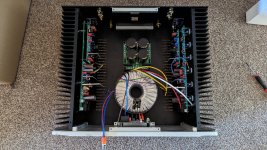
Layout.
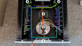
1. Soft start (situated either at the back or front panel)
2. Traffo with electrostatic screen
3. Power supply
4. Speaker protection (18 v DC)
4p - Speaker protection low capacitance power supply
Switch most likely will be at the back panel.
I understand it is ok to:
A. Run AC (RED) wires, twisted straight through the middle via soft start then back to transformer and rectifiers
B. Run wires (ORANGE) from 15V secondaries of the transformer to tiny PSU (4P) and after that run (twisted) along the red wires then split to left and right channels as shown
C. BLUE signal input wires to run along the perimeter as shown, twisted.
D. Amplified signal (GREEN) twisted to run alongside the blue path to the pair of speaker protection and then into speaker hook up points.
As well, can you recommend the location and type of ground without using fancy boards as I don't have them?
Suggestion how to proceed with electrostatic screen 2 wires from the transformer, where to hook them.
Thank you
Attachments
A couple of notes for @stuartmp and others that may care.
In the older build guide there is mention of D10 and D11 not turning on with a 30V bench supply. A side effect of that is that the VAS may not be biased properly, and as a result, the DC balance cannot be zeroed. This depends on the target rail voltage to some extent, but I have seen it on 1 of 2 EF3-3 targeted at 70.7 volts. A note in the build guide might save someone some time trouble shooting this non-problem.
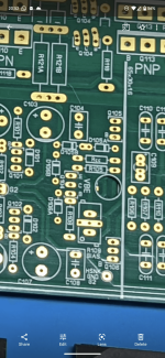
A while back someone claimed there were no silk screen errors. You may have been joking. Unfortunately, there are two sets of 126A and 126B on the EF3-4 boards V4.0. It's not a problem if you are paying attention and know the difference between emitter resistors and output networks.
In the older build guide there is mention of D10 and D11 not turning on with a 30V bench supply. A side effect of that is that the VAS may not be biased properly, and as a result, the DC balance cannot be zeroed. This depends on the target rail voltage to some extent, but I have seen it on 1 of 2 EF3-3 targeted at 70.7 volts. A note in the build guide might save someone some time trouble shooting this non-problem.
A while back someone claimed there were no silk screen errors. You may have been joking. Unfortunately, there are two sets of 126A and 126B on the EF3-4 boards V4.0. It's not a problem if you are paying attention and know the difference between emitter resistors and output networks.
There was a reference to the LEDs not blinking during clipping. If the clipping makes it back to the VAS, then D10,D11 get very much brighter during clipping.
For those of you looking for parts, I may be able to help. I have a fairly complete inventory of the Vishay resistors and and on-semi transistors and diodes. PM me if you are interested in getting some or all of the parts. I also have caps and some hardware.
A couple of notes for @stuartmp and others that may care.
In the older build guide there is mention of D10 and D11 not turning on with a 30V bench supply.
They clearly wrote "older" guide. I don't know about more recent guides, but In version 24, it says precisely this... perhaps that ties in...The build guide says nothing about setting your DC offset with low voltage and I have no clue why you would anyhow.
"Immediate lighting of all 6 LED’s. All the LED’s should light in a uniform manner. However, if you’re using a power supply of less than 35 V, be aware that D10 and D11 may not light, as they likely do not have sufficient voltage to turn on. This is not a concern. If the rest of the LED’s do not light, immediately shut down and investigate. Check to make sure that the LED’s are installed with the correct polarity. This can be done using your DMM in the diode test mode. If the LED’s are installed correctly, go back over your work to check for errors"
A while back someone claimed there were no silk screen errors. You may have been joking. Unfortunately, there are two sets of 126A and 126B on the EF3-4 boards V4.0. It's not a problem if you are paying attention and know the difference between emitter resistors and output networks.
106A and B? Maybe they edited w/o notation, but that's not what their post says (emphasis added is mine). I have not checked my boards, but I will.I do not see 2 sets of 106A and B on the board. There was a 105 A and B.
As I recall a reply on the same question > Directly to the chassis.Suggestion how to proceed with electrostatic screen 2 wires from the transformer, where to hook them.
On the EF3-4 V3.9 board there is actually two sets of R126A and R126B. One set is to the right of Q115 and the other set is below C113.
Rectifier heatsink.
The metal backplates of the rectifiers are not connected to any pins (measured it). Can I use just 1 plate or should I seperate them for extra safety?
I could also use some mica insulator but I prefer to just use some thermal grease.
What's best practice, risk etc...?
thx in advance


The metal backplates of the rectifiers are not connected to any pins (measured it). Can I use just 1 plate or should I seperate them for extra safety?
I could also use some mica insulator but I prefer to just use some thermal grease.
What's best practice, risk etc...?
thx in advance
I would have placed the heatsink a little higher so that air can circulate more freely underneath and heatsink is not so close to resistor.
Yeah... saw that. I will cut a piece to have some space there.not so close
On the EF3-4 V3.9 board there is actually two sets of R126A and R126B.
EF3-4 silkscreen from the latest guide (v33)
Hi guys, is there a reason I should not use 71-CMF55-39471%T1TR as RCC resistor? It is a fusable / current limiting resistor and an option for R19, R111a and R111b but not for RCC. I have these and would prefer to use them instead of ordering something.
Tried to connect and test one of the channels via peu + transformer. Blue fuse, but I forgot to change 2a to a bigger fuse. Swapped fuses and wanted to test if I burned anything, connected the bench PSU and now it is tripping at low voltage and d108 is blinking. I all call it a day and will resume tomorrow. Hope nothing serious
- Home
- Amplifiers
- Solid State
- DIY Class A/B Amp The "Wolverine" build thread