All checks ok. Time to connect it to the source, but I forgot to buy binding posts 🙂
This is the way
This is the way

This is the way 😀All checks ok. Time to connect it to the source, but I forgot to buy binding posts 🙂
This is the way
The hard work is done. Outputs installed. Final tests about to start using a variac. Any tips, advice or suggestions more then welcome before I put a lload on it. I almost know the guide by heart but I guess I'm a bit scared to do the final tests....

@wkloppen you have done extremely well to get to this point. Maybe just confirm the rail voltages you intend to run using your DMM before you actually connect the rails leads to the amplifier modules. I personally would start one channel at a time and connect all the DMM's to the relevant locations on the amplifier board being tested before you turn it on.
These locations will be noted in the build guide. Double check that R109 is set to Maximum resistance so you start up safely with little to no bias on your output transistors. Make sure your clear in your mind which DMM is measuring what. Turn on and keep your eye on the dc offset meter first.
Lastly read the build guide section on start up a few times so it's clear in your mind what to expect and do.
Good luck 🤞
Will do that! I ran the no output tests with 0.5 amp fuses. Now the 2 amps. Cant wait to hear some sounds.Maybe just confirm the rail voltages you intend to run using your DMM before you actually connect the rails leads to the amplifier modules
The support on this mature forum has been a joy sofar...
w.
You will not be disappointed!
Can the manual be updated for Q103 being new thermal sensor? I guess voxx can still change it.
Can the manual be updated for Q103 being new thermal sensor? I guess voxx can still change it.
Yes, I plan to made the changes to my boards on the weekend and take photos as I go so I can update the build guide.Can the manual be updated for Q103 being new thermal sensor? I guess voxx can still change it.
Luckily you got one working. Should be easy to compare voltages between the boards and pinpoint where the issue is.
Firstly congratulations on getting one board up and running.Can't seem to get any bias. DMM connected to TP101 and TP 102. J103 removed. Outputs stay cold and I've turned R109 multiple times anti clockwise.... strange.
With your second board. What are the other test points measuring. Typically to start up safety you would have
1. A meter across your rails.
2. A meter checking DC offset
3. A meter checking the LTP current
4. A meter checking the output transistors bias.
All at the same time otherwise something could go wrong and you have no information feedback from those other points.
How many times did you turn the pot at R109 there can be depending on your transistors quite a dead zone.
You may want to check the other test points are as per the build guide and the try adjusting the bias again.
Good luck 🤞
Just got home from a night with the boys here in the Netherlands. Will run the tests tomorrow. I have just one dmm. DC is fine. Close to zero. TP1 to TP2 adjusted to 5.00 volts. The input stage heatsink is hottish just like the working channel. Rail voltage of the none working board is 58 volt while the working board has 57.40 which is I think an explainable voltage drop of 0.6 volt due to the bias current draw.
Did some general checking on components and their position but not on a detailed level just yet. Need to read the trouble shooting section of the guide one more time.......
w.
Did some general checking on components and their position but not on a detailed level just yet. Need to read the trouble shooting section of the guide one more time.......
w.
You will need to turn the bias pot in the opposite direction compared to the other board, you may need to keep going slowly until you see some bias. Refer Stuart's comments above too. I have just biased and burned mine in again in the case after the vbe mod. Take yourThe other channel appears to be working. More or less stabilising on 44 mv with the pcb heatsinks and the main heatsink warming up. Need to inspect my work....
View attachment 1186132
Time you are very close 😀
Last edited:
I know... turned the pot from lock to lock already. Need to clear my head as all the exitement of being close might just blur my brain a bit...opposite direction compared to the other board

Something is definitely not right.turned the pot from lock to lock already
Please check.
1. Your rail fuses.
2. the output transistors are in the correct locations PNP, NPN etc
3. Check that Q103, Q104 are installed in the correct orientation especially Q103 ensure E, C, B top to bottom on the board matches the legs on the transistor E, C, B left to right
4. Check what voltage you have across Collector to Emitter on Q104 and see if it matches your schematic. If not report back what the voltage is. Does adjusting R109 change that voltage at all.
Attachments
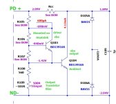
Think I found it doing some off power basic measurements. Q103's Base and collector are shorted somehow. Possibly something to do with the flywires......
1) 58 volts
2) Correct positions
3) Orientation / legs appear to be correct matching the silk (same as working one)
4) Yet to do after I fixed the metnioned short
TBC....
Thanks guys!!
w
1) 58 volts
2) Correct positions
3) Orientation / legs appear to be correct matching the silk (same as working one)
4) Yet to do after I fixed the metnioned short
TBC....
Thanks guys!!
w
Transistor is fine. Removed one R106 leg....still a short and the resistor R106 is fine.
to be continued.....

to be continued.....
Found it!
A single strand from the base wire didn't enter the hole when I soldered the flywires and decided to have some fun at the collector🙂🙂

A single strand from the base wire didn't enter the hole when I soldered the flywires and decided to have some fun at the collector🙂🙂
- Home
- Amplifiers
- Solid State
- DIY Class A/B Amp The "Wolverine" build thread