Hi to all members.
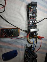
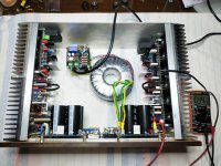
I fire it up the two modules.
Voltages +/-71.5V
Drivers Mje15034 and Mje15035
At the position D115 D116 i put 10Ω resistors.
Tp107-108 775mv adjusted, at the begining 380mv with trimmer 500Ω with Q104 mounted.
Tp1-2. 5.0V at the begining 3.8V
Tp3-4 590mv at the begining 606mv
With TCC004B and positive voltage 1.360V
With TCA004B and negative 1.390V these voltages cycling about 30-40 mv. I don't know why..... any suggestions???
Offset hahaha 0.1-0.6mv at the begining about 6-8mv
Attachments
Last edited:
Hi my friend BillNikos,
I like the way you bent over the heat sinks, did you just do it in a vice? I am reusing a case and will be a little cramped. I hope there is no negative reason not to. Bleader resistors are great during build and testing, I like to take them out when putting them into service and eliminate one more heat source inside the case.
Bill
I turned these small aluminum pieces at right angles in a large industrial machine
Thanks for your kind words.
BR Nikos
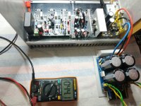
Today I'm watching the behaviour of bias current.The position of the Q104 its critical for me i have small heatsinks and big testing voltages +/-70V.i think to put the transistor Q104 over the output transistors its not good Idea....i prefer the heatsink between Pnp and Npn transistors.
Attachments

The old bias circuit was overcompensated by a lot. You may want to update the bias circuit to the new one in the updated BOM.
Since we are back on this topic, by any chance did the team also test thermal compensation with Rcc replaced with a wire, as in the original bias circuit by ostripper ? This would also reduce the overcompensation, right ?
Nothing against the new bias circuit; I implemented it and it seems to work fine. But I liked the idea of separate compensation for drivers and outputs.
Nothing against the new bias circuit; I implemented it and it seems to work fine. But I liked the idea of separate compensation for drivers and outputs.
Working on the video but a few road blocks over the last few days....
I will give you a tip though, twist the power supply lead rather than plait them and maybe use some sleeving on them.
Also run the dc psu wires on the side of the heatsink which has the output transistors like in the right hand side of your picture above
This keeps them away from the very sensitive feedback trace.
Your build is going great by the way, it will be worth it
Hope this helps,
- Dan
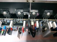
Αfter hours of monitoring the bias current I concluded as follows. The best placement of heatsinks is with the transistors down, this way the heatsinks perform better ..unfortunately with this way one input will have to go from the side of the transformers..
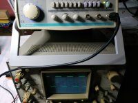
ii. Measure the AC voltage in millivolts across TP104 (output) and TP100 (Speaker ground) ideally this should be less than 0.080 mV. If this value is greater than 1 mV and depending on the sensitivity of your speakers you may hear a small amount of hiss coming from your speaker’s tweater.
My measurmetnts show me about 0.110mV and 0.130mV
Attachments
Last edited:

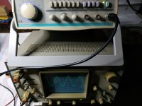
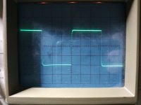
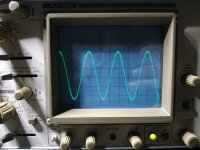
Very nice...10khz sine, 1 khz square , 1 khz sine , 10 khz square .NO LOAD
Attachments


Last edited:
@stuartmp
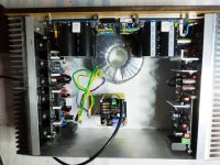
Ιt's still early for music, I'm not in a hurry, other tests with load and capacitor will follow. Besides, the power supply must also be changed. The transformer haha is borrowed from the Mimesis 9.2 clone and is also large in voltage of 2x50 AC volts, but so far everything is fine ....
Certainly the quiescent current does not stabilize at 44 mv (100ma per transistor ) as expected with the volts +/-71V applied to related to the limited heatsinks I have 40mm 155mm 280mm . The new circuit with Q103-104 BD136S shows that it works very well and actually stabilizes the quiescent current at 32mV on this heatsink with the transistors down....the other module stabilizes the quiescent current at 29-30mV transistors up. ( Ambient temp 26-28 C and temp on heatsinks about 42-43 C)
I have some relevant experience in building amplifiers TITAN 2000, P3A ,Mimesis 9.2 and (USSA 5.0 Also an organized work) but this is the first time I see in this forum such an organized work, very easy for anyone to build this amplifier.
Νow i have to decide what voltage i should go to transformer 42VAC or 45VAC (59V DC or 64V DC ) please i would like your help on this matter from all of you. EF3-3 board and 40mm 155mm 280mm heatsinks.
Last edited:
Is anyone opting for an alternative way of attaching the ground points for the heatsinks? First, for the HS for Q105/Q106 - are you using a small wire soldered to a ring terminal and then screw to the HS? Second, is the 2-pins on the bottom of Q107/Q108 - unlikely I can drill that small edge effectively, so hoping for an alternate method.
Show me your alternate ways of grounding the HS? Looking for a good, solid, but easy method - or if it's possible to ignore grounding the HS (understanding risks associated)?
If it matters - all transistors on HS are fully encapsulated versions (13916S, A1381/C3503, A1837/C4793).
Show me your alternate ways of grounding the HS? Looking for a good, solid, but easy method - or if it's possible to ignore grounding the HS (understanding risks associated)?
If it matters - all transistors on HS are fully encapsulated versions (13916S, A1381/C3503, A1837/C4793).
If you have access to a bench drilling machine, drilling a hole in the edge of a 3mm aluminum plate is not that difficult. Take your time and go slowly.
Otherwise you might consider using a 1.5mm heat sink for the drivers. Mechanically not the best option, but cooling will be equally efficient. Maybe some standoffs between heat sinks of drivers and pre-drivers can help for mechanical support and grounding ?
Otherwise you might consider using a 1.5mm heat sink for the drivers. Mechanically not the best option, but cooling will be equally efficient. Maybe some standoffs between heat sinks of drivers and pre-drivers can help for mechanical support and grounding ?
The first set I did I just took a wire around one of the mounting screws for the encapsulated transistors. I used copper for the driver heatsink and soldered heavy component leads for that support/ground attachment. I needed a torch to get the HS hot enough to solder. First try was with a diode lead, and that didn't work very well since the diode leads were tin all the way through. They melted in the torch 😢
With a drill press you can drill the edges of the 3mm Al. I then used the specified pins pressed in and dimpled the Al above the pins on both sides using a punch and brass hammer. I tried to pull them out and they were fine and I assume making adequate electrical contact.
The transistor leads are enough support, at least for the smaller sinks. Just be careful after they are installed.
Hopefully my last question about the build portion.
Can someone tell me what the value of C11 is? On the IPS schematic it says "see BOM" and on the 4 BOMs I have there is no C11 listed part. Additionally, when I look at the notes on the schematic, it says it was added on 11/21/21 but again no value notated that I can find.
Thanks for the help on the grounding and support pins for the HS.
- Home
- Amplifiers
- Solid State
- DIY Class A/B Amp The "Wolverine" build thread