Perhaps not. However, I like to check as much as possible before leaving the comfort of my CV/CC bench supply. I know that I'm not setting the final DC offset, but checking that it would go to 0 at some setting seemed reasonable. Many amp circuits I have studied have Q12 referenced to ground, in which case above some minimum voltage (often as little as +/-3V) everything in the IPS/VAS works, just like any other opamp. However, Wolverine uses a different scheme in order to allow low voltage/low noise transistors to be used in the VAS as well as in the IPS.The build guide says nothing about setting your DC offset with low voltage and I have no clue why you would anyhow.
Another note is that the check of the VAS CCS at too low a voltage may result in less than 600mV across R16. This is also not mentioned explicitly in the build guide. In fact, from the second paragraph of section 16 of the rev 33 build guide, it is implied that 20-30 volts is enough to perform these initial checks.
Right, yesterday I was most likely getting tired - and connected something in the wrong way.
Earlier today I removed boards to check if any visible damage- everything looked ok. Adjusted all trimpots to base values.
Just out of interest connected the bench psu again, o check the voltage drops and what do you think- the board works without any issues.
So, it seems yesterday I blew 2A fuse despite a soft start module installed. Is this normal ?
I will try another power-on on Tuesday evening.
For ground connection, am I correct to do it this way:
My psu board has a ground connection in the middle of the 4-cap bank. I will connect the lead from it to connect it to the chassis directly underneath the power supply board. IEC inlet will be another wire to connect there, as well as a transformer shield and a tiny speaker protection psu.
Thanks!
Attachments
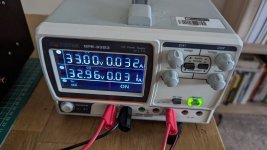
Maybe a stupid question, but do you get "negative" voltage from your bench psu by connecting it this way? 🤔
Okay👍 I thought it had to be a PSU with lets say -32V COM +32V connections. Like for example the Keysight E3630A.
Hmm okay, I'm far from an expert in this matter, but I don't see any COM and negative voltage terminal in your picture. Try to google Keysight E3630A and you will see what I mean.


@NSP and @voxxonline thank you for asking and answering such questions. Such posts are really helpful for people like me without any background in electronics. So keep them coming 😉
Well, my electronics knowledge is probably not too far off from yours mate 🙂
It looks like you have the right connections to your bench supply, but it is hard to see the labels on the front as they are under the plugs. Supplies vary in their wiring and capabilities. This looks like it follows the scheme from my old MASTech supply, which I replaced with a Rigol some time ago with the series parallel push switches.
Probably, I am not an expert 🙂 just connected my left channel to the amp power supply, all good, no issues. Will do the right channel tomorrow.
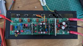
Initial testing finally started. No load PSU tests first. Appears to be working....
.jpeg")
.jpeg")
.jpeg")

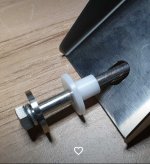
Make sure that in the final version the top cover of the amplifier does never (ever) touch the round metal plate and bolt on top of the transformers. Otherwise your chassis will form a short-circuited transformer winding and (depending on whether both transformers are in or out of phase) a huge current will flow in this winding.
Thx for tip. Didn't know that. Will cover it with some tape and foam.does never (ever) touch the round metal plate and bolt on top of the transformers.
w.
Is it normal the bleeder R's are getting hottish. I'm using the 2.2k 3W's. Leds are down in about 1 minute. With 58V/2.2K = 26ma is not that much so I can't seem to understand why they are hottish when the psu is switched on!?
Or is this all normal behaviour?
w
Or is this all normal behaviour?
w
You can also make a insulating spacer so there is no chance of a shorted turn.Thx for tip. Didn't know that. Will cover it with some tape and foam.
w.
Attachments
- Home
- Amplifiers
- Solid State
- DIY Class A/B Amp The "Wolverine" build thread