While waiting for the final part,...some alu plates to heatsink the rectifiers...thought I'd make the simple current limiter which I didn't have yet🙂🙂


Thanks felix1024 for sharing your mosfet protection circuit. Got me thinking, fireanimal did you install speaker protection in your builds, and did you measure distortion with and without it by any chance ?
Hi kokkie,
well the type of MOSFETs used to switch speaker is a low Rdson type which will be typical less than 10mOhm. (milli Ohm) This is equal or better than mechanical contacts of a relay. Furthermore it has no inductive or capacitive part in the resistance, therefore it will not have any influence to THD or THD+N. (I'm going to verify fireanimals measurement as soon as my test parc allows such low THD measurement)
By the way the MOSFET is specified for Ids max of 83A! that current would burn most relays used in speaker protect circuit at all. The SSR type relays also does not have the problem of electric arc in case of switching of in order to protect speakers from rail voltage if an output BJT is shorten.
@fireanimal: maybe you could help me in setup measurement. I have QuantAsylum Q401, and now also build Bob Cordells Distortion Magnifier. Will this be enough to measure Wolverine EF-4 THD and THD+N?
-Felix
I don't run speaker protection on any of the amps I built, I know its not the best idea, but to me the less in the path of the signal the better. On the other hand though also don't want to risk $$$$ and blow my speakers for a few extra points of THD. I do currently have some of @Bonsai speaker protect board, that I want to build and test. But I also am interested in @felix1024 boards to try, and measure what effect it has on the overall THD measurements.Thanks felix1024 for sharing your mosfet protection circuit. Got me thinking, fireanimal did you install speaker protection in your builds, and did you measure distortion with and without it by any chance ?
In theory. You are not accounting for any added loop area, or trace layout issues on the PCB that could cause higher THD and especially added noise.Furthermore it has no inductive or capacitive part in the resistance, therefore it will not have any influence to THD or THD+N.
It will get you most of the way there with THD measurements but not THD+N.@fireanimal: maybe you could help me in setup measurement. I have QuantAsylum Q401, and now also build Bob Cordells Distortion Magnifier. Will this be enough to measure Wolverine EF-4 THD and THD+N?
Also I would be interested in a speaker protect board to test out.
Thanks!
I'm pretty sure you will not hear any difference between using a speaker protection or not. This amp is so low already that tweaks being made are icing on the cake.
Gents,
I have finally got to power up with output transistors installed. The initial power-up was pain-free.
Now, I have soldered NJW0281G and NJW0302G , and hooked up everything to my bench power supply @ 33v 0.3 amp limit.
For some reason, I cannot read any bias between TP101 and TP102. Though all LEDs except D10, and D11 are on.
5V adjustment setting is done.
What can I check to identify a problem? Not sure how many turns I need to do on R109- did 5 turns both ways- no change @ bias.
For my power supply, I have used Prasi CRC in rectifier + capacitor configuration.
Can someone please confirm I have soldered everything as it should be:
Jumpers on R1 to R6
C1 to C4 installed
B1 & B2 installed
C5 & C6 installed
R10 & R11 installed
RB & RB' installed
LED installed.
Thank you in advance.

Can someone please confirm I have soldered everything as it should be:
Jumpers on R1 to R6
C1 to C4 installed
B1 & B2 installed
C5 & C6 installed
R10 & R11 installed
RB & RB' installed
LED installed.
Thank you in advance.
Attachments
I'm using the same psu boards. My rectifiers are postioned the same. I can't see how you can mount them the wrong way as there are markings all over the place🙂shiny side is towards the capacitor side?
well the type of MOSFETs used to switch speaker is a low Rdson type which will be typical less than 10mOhm. (milli Ohm) This is equal or better than mechanical contacts of a relay. Furthermore it has no inductive or capacitive part in the resistance, therefore it will not have any influence to THD or THD+N. (I'm going to verify fireanimals measurement as soon as my test parc allows such low THD measurement)
-Felix
You maybe interested in this test for harmonic distortion of a solid state relay - https://www.diyaudio.com/community/...r-protection-and-delay-gb.340694/post-5875582
YesWhat are those flat bridge rectifiers mounted? The shiny side is towards the capacitor side?
Well the SSR part is nearly identical beside it is all SMT, which I tried to avoid for DIY friendlyness. My design is digitally controlled and completes the missing overcurrent protection of the Wolverine. No difference on measurement with or without SSR as I can see.You maybe interested in this test for harmonic distortion of a solid state relay - https://www.diyaudio.com/community/...r-protection-and-delay-gb.340694/post-5875582
@fireanimal: I can provide you a technical identical beta speaker protection board from the development phase (has some corrected PCB trace errors in the logic part. If you are able and willing to make measurements of THD, THD+N and noise with such speaker protect board added, I will send it to you. (PM me for shipping address)
BTW: the traces from screw terminal to screw terminal IN to OUT are straight less than 100mm and as low impedance as possible.
Hi Guys, two questions:
Can I use this 0.6watt 0 ohm resistor as J101 and J102?: 594-MBB02070Z0000ZC1
There is no mouser stock of the BOM suggested MUR460's, can I use 821-MUR460R0G instead?
Can I use this 0.6watt 0 ohm resistor as J101 and J102?: 594-MBB02070Z0000ZC1
There is no mouser stock of the BOM suggested MUR460's, can I use 821-MUR460R0G instead?
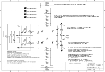
@felix1024 : the overcurrent detection circuit is really nice. The four resistors implement a single slope VI limiting isn't it ? Where did you find your inspiration, and did you adapt the values to fit the SOA of the Wolverine output devices ?
@ghitus, yeah I know I can use a normal wire, but I have a whole bunch of 0r resistors that I think are exactly meant as jumper wires, so I think I can use them and it will look neat. Just want to make sure it wont lead to problems. If not a good idea than I will just clip the leads of some component and use that
@felix1024 : the overcurrent detection circuit is really nice. The four resistors implement a single slope VI limiting isn't it ? Where did you find your inspiration, and did you adapt the values to fit the SOA of the Wolverine output devices ?
The circuit was published by Bob Cordell in his book "Designing Audio Power Amplifier" (Second Edition) p. 97ff it monitors voltage over the outputs BJT emitter resistors. The Vbe on Q4 will be rectified amp output proportional to current in the output stage. Time constant of R7/R17 to C2 will be about 2mS, as soon as Vbe@Q4 reaches 0.55V the optocoupler switches on. This happens when current produces 2.5V on the 0.22Ohm emitter resistor according to 11.3A Ic on a output. The uC gets logic high on PB1 which triggers PA4 to disable SSR. (needs just 30uS)
I use MJL4281/MJL4302 as outputs, SOA will allow >10A for nearly 10mS, so this will work. Verified by doing short circuit tests direct on the output terminals multiple times. I haven't checked for all the other variants.
- Home
- Amplifiers
- Solid State
- DIY Class A/B Amp The "Wolverine" build thread