One more question concerning C9, it's 100uF/63V NPO. Is it really necessary to use 63V cap there? Could I use a 50V NPO cap instead? I have plenty 50V Muse and even Black Gate 100uF NPO caps which would fit nicely there.
Thank you,
Thank you,
Given the circuit, there is a maximum of a diode forward drop across C9. The voltage spec comes in with the claim that AlO capacitors have lower distortion in the higher voltages. Self has indicated and tested that the key to low distortion across AlO is to keep the signal voltage across the cap very small, regardless of the voltage rating of the part. That criterion is met in this circuit, with < 0.375 volts at 20 Hz at 65 volt peak output. That's over 250 watts into 8 ohms.
If you have a 50V cap that fits, I see no reason not to use it. I am happy to be proven wrong by any actual data.
If you have a 50V cap that fits, I see no reason not to use it. I am happy to be proven wrong by any actual data.
These diodes help isolate the input/pre-driver power rails from the the output stage rail ripple. The input caps for the cap multiplier charge up when the output rail voltage is high, and the diodes block discharge when the output rail voltage drops. You want fast Schottky diodes to minimize noise at higher frequencies and to limit the power supply drop going into the input stage. Bigger diodes may not be as good as the smaller diodes. There is very little current (relatively) through the diodes. The input stage only draws about 12 mA.Thanks,
if these diodes are to replace these two resistors than SB1100 or SR3100 (3A 100v) should be good enough replacements, am I right?
I understand why Schottky diode was used here. These diodes are extremely fast due to their metal to semiconductor junction so their blocking capabilities are much better than those of fast recovery diodes. Consequently, my understanding was that any small Schotkky diode capable of handling PS requirements should do. As MBR1100 is not available I believe that one could use similar to MBR1100 diodes such as SB1100 or SR1100 or even higher current ones.
That is true that higher voltage caps have lower distortion so I always use notably higher voltage caps than the minimum requirements. In the case of C9 the main problem is that the best NPO circuit caps do not exceed 50V (and I have plenty of these including 4 Black Gates). There are speaker crossover caps, which have to stand higher voltages such as 100V but these are much larger and usually axial. Of course there are some NPO radial caps such as the suggested one. But when it comes to low frequencies also capacity of C9 matters and the higher capacity the lower distortion one gets at lower frequencies and Douglas Self's experiments showed that as well. LT simulation also shows that.
Two of my EF3-3 amps will work above 400Hz so 100uF capacity of C9 is good enough but my EF3-4 will also be used as a stand alone amp and I'd like to compare it with my friend's Electrocompaniet. Electrocompaniet is substantially faster than this Wolverine amp and has a high damping factor above 1600. So in this case I would be tempted to use a 470uF cap for C9 or even a 1000uF one composed of two 470uF in parallel. Alternatively instead of a NPO cap one could use two twice larger low ESR polar caps as C9. The practical problem is that there is not enough space on the pcb. Parallel caps, however, can be installed as one cap could be installed on the track side of the pcb.
One more question. I copied all the updates from the Wolverine project dropbox and got to that R21A and R21B section. My question is why two 13.7k resistors are used instead of one 27.4k (or 27k) resistor when a parallel R-C (100ohm 1pF) circuit is added across both R21A and R21B resistors joined together? Shouldn't the R-C circuit be across the R21A resistor only? Wasn't that the reason for splitting R21? Please explain.
Thank you,
The "flagship" , of course. 210Kuf and 16 pairs of output BJT's.
AW 800 = 24K$.
Bet they sound the same , AW might like 1R load better.
OS
AW 800 = 24K$.
Bet they sound the same , AW might like 1R load better.
OS

I looked at the AW800. Sort of reverse engineered it.
same as the Wolverine -
1. special attention to the layout , they actually seem to have split the ground as we have.
2. the best of parts - I see our builders have done the same.
3. they went overboard with outputs and capacitance , quite the toroid (2K VA) damn !!
I think we got about the same for <1K$ , but they might drive 1R loads better. Oh , well !
We did not spend 24K $ !!
PS - loved looking at that amp (amp porn) , I can do better with my new "credit card" SMD amp stages.
I'm a gonna do a SMD cool "credit card" Wolverine to finish my assault on audiophile BS !
OS
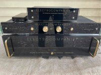
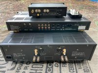
I do not remember which Electrocompaniet amplifier model it is, certainly it is not the $24k one as I vaguely remember that the price he paid was in the A$10k range many years ago. I'll ask him tomorrow. The amp is fully balanced and has marble or marble-like front panel. He's got a matching Electrocompaniet preamp going with it as well. Apart from Electrocompaniet he has a few other amps and preamps etc.
I do not think balanced amplifier makes much difference in Perth suburbs except for phono, especially MC, where external interference could make some difference. But from my personal experience these are the speakers and room acoustics, which matter most and make almost always some audible difference. Of course all other parts of any audio system matter but at a certain level up one can not tell them apart, while even small differences between different speakers and room acoustics are heard.
cheers,
My guess is that the two 1/2W resistors are equivalent to a single 1W resistor, and cost less. These two resistors have a lot of voltage across them, making them slightly susceptible to thermal distortion. It may also be useful for testing. There are some compensation schemes that split the FB divider, but this is not one of them. The 1pF in series with 100 ohms doesn't kick in until very high frequencies. If I did the math correctly, the corner is somewhere around 5.8MHz for the 22k input impedance. The main compensation for this circuit is from C4, C5 as transitional Miller compensation.One more question. I copied all the updates from the Wolverine project dropbox and got to that R21A and R21B section. My question is why two 13.7k resistors are used instead of one 27.4k (or 27k) resistor when a parallel R-C (100ohm 1pF) circuit is added across both R21A and R21B resistors joined together? Shouldn't the R-C circuit be across the R21A resistor only? Wasn't that the reason for splitting R21? Please explain.
Thank you,
As for feedback cap, Self found that the voltage across the AlO cap doesn't significantly increase distortion until it exceeds about 1/2 volt. The previous calculation gave less than that at 20 Hz at full output from 70V rails. You are welcome to use anything that fits. Larger capacitance makes the voltage less, so if you are concerned, increase the capacitance. The difference between 63V and 50V is unlikely to matter in this application, and is obviated by the lower voltage from the larger capacitor.
My only consideration against the larger Schottky diode was higher junction capacitance. The SB1100 has a higher forward voltage drop than the the MBR1100 by around 0.05 to 0.1 volts. It will work, just not quite as well, and it is a very small difference.
Mhuth1776 you are correct regarding the feedback resistors.
For those interested, there are threads on this site discussing the advantages of having resistors in series for that position.
For those interested, there are threads on this site discussing the advantages of having resistors in series for that position.
One of the reasons that the team chose a 63Volt cap was that it was concerned that inexperience builders might make a mistake in assembly and one of the rail voltages might appear across this cap etc.One more question concerning C9, it's 100uF/63V NPO. Is it really necessary to use 63V cap there? Could I use a 50V NPO cap instead? I have plenty 50V Muse and even Black Gate 100uF NPO caps which would fit nicely there.
Thank you,
You can use your favourite 50V cap in that position. Some of the team have done so.
However, you will need to test your Black Gate caps before assembly. Rubycon has not made Black Gate caps for many, many years.
For D115 and D116 any of the below Schottky diodes should be OK. They are not in a critical part of the circuit.I'm on my way to order parts from mouser, but the MBR1100G (D115, D116) is out of stock. They expect more next year. 😴
Are there any replacement diodes for these?
863-MBR1100G
621-SB1100T
750-SB1100E-G
625-SB1H100-E3/73
or anything similar
Last edited:
Yes, Black Gates are not in production for many years. Mine are among the last produced but might need reforming. Their ESR is 0.01-0.02ohm now. My Muse caps have similar parameters and are much younger. Anyway, I'll use one of my 50V BP caps for C9.
As for R21 I'll probably use one 27k 1W resistor and for R9 I'll have to use 910 ohm as I have to increase the gain to match it with reduced gain of my other amps. Stability will not be adversely affected while small increase in distortion is the price I have to pay.
Back to Electrocompaniet. My friend has one of the basic models, namely AW100dmb model special edition or so with marble-like front panel. The system is on the attached photos although I took that photo from the internet. It's fully balanced dual mono amp with damping factor crazily high: 8000 and in this version power output is about 120W RMS into 8ohm.
cheers,
Attachments
The function of Rcc is to keep the output of the vbe multiplier stable if the current source changes due to fluctuations in rail voltage.
The intrinsic emitter resistance re’ of Q104 is about 6.5R. The vbe multiplier will increase this by the Vbe multiplication factor of ~6
So 39R. This means that if current through the collector of Q104 increases by 1 mA, the bias spread will increase by 39mV. This is a significant fraction of the 44 mV output bias voltage across the emitter resistor.
So in summary as the collector current changes the value of re' changes.
The output of the vbe multiplier then also changes. So a value of Rcc is selected so that any changes to the collector current through Q104 which changes the value of re' are mitigated by the voltage drop across the Rcc resistor so the output of the vbe multiplier remains the same.
Hope that helps
Hi Guy's,
I just update the schematic with the new VBE multiplier components that @fireanimal posted a few weeks ago.
Check your Dropbox folder for the latest version.
I just update the schematic with the new VBE multiplier components that @fireanimal posted a few weeks ago.
Check your Dropbox folder for the latest version.
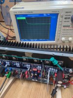
I did a simple load test with the new Vbe multiplier on my EF3_3, first with Q103 on the heat sink between Q113 and Q111, then with Q103 on top of Q111. First I adjusted for each case the bias to 44mV without signal, with burn in and all. The I applied a 1kHz sinus tone of 50W in a 4 ohms load until the heat sink heats up to 50°C (measured with a thermocouple taped on the surface). I suddenly stop the function generator and plot the bias between TP-101 and TP-102 as a function of time. On the scope 20mV/div on the vertical axis and 10s/div on the horizontal. As you can see, with Q103 on the heat sink the bias returns smoothly to the steady state value. With Q103 on top of an output there is a slight dip towards 35mV but overall still a nice result. With the old configuration the bias dipped below 20mV. Good work you guys.
Attachments

Amp porn. Too bad the LEDS don't flash at clip.
Is that some sort of oscillation or SMPS noise on the scope ?
Is that some sort of oscillation or SMPS noise on the scope ?
Run high enough rails and that's not a problem 😎Amp porn. Too bad the LEDS don't flash at clip.
- Home
- Amplifiers
- Solid State
- DIY Class A/B Amp The "Wolverine" build thread