I am ordering components for my boards, and have encountered an issue. I plan to use my fisrt unit initially as a 18db low pass for the 18" H-frame true woofers below my Altec 605B OB panels. Currently I use the 24db low pass buit into Crown XLS-1002 amps. This works fairly well, but I think the flexibility of the 6-24 promises improvement.
Aiming the corner at 38-45 hz, it looks like I want C1 to be 170-200nf. Looking at both Digikey and Mouser, it looks like there are no Wima FKPx caps in that range. Between the available values (220 and 150), i would think that 150 makes the most sense, but lead spacing is too big. Two questions, then:
1) Should I use the larger FKP camps and adapt into the boards?
2) If not what alternative Wimas or other brand caps are a good alternative?
Thanks In advance, and best wishes for 2021!
to Skip Pack
Hello Skip Pack,
for the 150nF with 5mm leadspacing you could try this:
Mouser Part No
505-MKP2C031501H00JO
Greets
Dirk
Hello Skip Pack,
for the 150nF with 5mm leadspacing you could try this:
Mouser Part No
505-MKP2C031501H00JO
Greets
Dirk
Thanks, I suspected it would be one of the MKP series but wasn't confident about picking which one.
Better Crossover with driver measurements
Real world speaker drivers do not match up the theoretical crossover values presented on the calculator. the results are not ideal PASS XO CALC
I would suggest the use of vituixcad software to substitute real drivers and the calculate the crossover. you could use 2nd and 4th order blocks from the library, only difference would be that opamp is replaced by jfet.
you could do the same with Xsim as well.
Cheers
Attachments

I have written that too in earlier posts. You need the use the real acoustic response of your speaker drivers. That is also why there are trim pots for setting the response of the crossover. In most cases the acoustic response of the two drivers will be the same, more rarely the electrical response.

Open Baffle Loudspeakers
I plan to build the 6-24 XO, boards on order. My speakers are open baffle design. I would like to ask are there any special considerations in building this XO for open baffle loudspeakers. I understand Mr. Pass has a cross over specially designed for open baffle speakers (B5). Any guidance on this would be appreciated.
I plan to build the 6-24 XO, boards on order. My speakers are open baffle design. I would like to ask are there any special considerations in building this XO for open baffle loudspeakers. I understand Mr. Pass has a cross over specially designed for open baffle speakers (B5). Any guidance on this would be appreciated.
Is not the LXMINI CROSSOVER better suited for an open baffle speaker? It can also equalize the response of the two drivers. The 6-24 XO cannot do that.
Hello 6-24XO-builders,
a member of this forum sent me a pm asking for the values of Rs and Cs in my
6-24XO build for subwoofer use (crossover frequency around 80 - 100Hz).
I post you my first results I've got, using Mike Rothachers software calculator.
The simulation is done for a 24dB/oct slope.
These values are a first result. I didn't test it by listening nor have any 'real life' -measurements been done. I can't tell you if this works with your loudspeakers!😕
Any hints from other builders are welcome! 😉
Greets
Dirk 😀
Would it be overkill to use the 6-24 simply as a high pass filter (24db slope at ~40Hz) for subwoofer use, while keeping the passive crossovers in loudspeakers?
I am thinking this would work between source and amp with volume attenuator (possibly building passive pre soon as well). I’d like to experiment with not sending full range signal to the mains 😀
....why overkill? Using Neumann KH 310 (3 way aktive speaker) I 'll use the 6-24 to use a ripol as subwoofer. It's interesting to experiment with woofers. The ripol is an outstandig priciple with an extreme "dry and impulsive" bass.
I'm waiting for the board and Jfet's and will report. A complete digital control with digital potentiometers has been finished and I' ll show pictures next week....
I'm waiting for the board and Jfet's and will report. A complete digital control with digital potentiometers has been finished and I' ll show pictures next week....
microcontrolled xcross-6-24
Here are first pictures of my "microcontrolled" Xcross-6-24.

The plan was simple: replacement of the trimmers by digital potentiometers (MCP42050) and replacement of the jumpers by relays (omron G6).
Rest was planning the software and 3 circuit boards.
A first board has an arduino 2560 as microcontroller and the potentiometers on board. My goal was, to reproduce the values of the potentiometers exactly and possibility of storage of different setups (10).
The connection digital potentiometer-> Xcross board is realised with flat cable over short distance. The same procedure between relays and jumpers.
A second board contains 3 rotary encoder, 4 push buttons and "information"-LED for the left side and the third printed board for the right side.

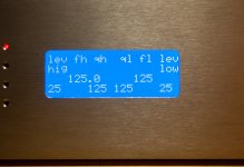
Information about actual setup comes via 20x4 oled display.
Meanwhile the software is running - I am waiting for parts from mouser and the original xcross board.
Meinolf
Here are first pictures of my "microcontrolled" Xcross-6-24.
The plan was simple: replacement of the trimmers by digital potentiometers (MCP42050) and replacement of the jumpers by relays (omron G6).
Rest was planning the software and 3 circuit boards.
A first board has an arduino 2560 as microcontroller and the potentiometers on board. My goal was, to reproduce the values of the potentiometers exactly and possibility of storage of different setups (10).
The connection digital potentiometer-> Xcross board is realised with flat cable over short distance. The same procedure between relays and jumpers.
A second board contains 3 rotary encoder, 4 push buttons and "information"-LED for the left side and the third printed board for the right side.
Information about actual setup comes via 20x4 oled display.
Meanwhile the software is running - I am waiting for parts from mouser and the original xcross board.
Meinolf
Last edited:
Hello Meinolf,
very interesting project! Digital control via arduino and audiosignal on the analog side. Sounds very interesting to me! 🙄
Greets
Dirk 😀
very interesting project! Digital control via arduino and audiosignal on the analog side. Sounds very interesting to me! 🙄
Greets
Dirk 😀
.....now I find the trick to attach files.
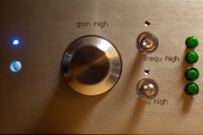
Picture Nr.1: the complete front, not milled perfectly but it represents the idea
Picture 2: diplay with different informations
Picture 3: big encoder for gain high, 2 small encoders for frequence and q high, 4 buttons 6-12-18-db with logic use of the potentiometers. Same process on right side for gain-low, frequnce low and q low.
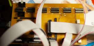
Picture 4(not sharp): the controller board, the arduino "hangs" on the bottom side, free places for MCP42050.
Pressing the encoders you take 3 informations: - gain/frequence/q as a bit information (1-255), a resistance information (0-50k) and calculated gain(dB), Frequence(Hz) or q information.
A choose of channel (left, right or stereo) is possible per parameter.
If both big encoders be pressed, the actual setup can be stored or restored.
Picture Nr.1: the complete front, not milled perfectly but it represents the idea
Picture 2: diplay with different informations
Picture 3: big encoder for gain high, 2 small encoders for frequence and q high, 4 buttons 6-12-18-db with logic use of the potentiometers. Same process on right side for gain-low, frequnce low and q low.
Picture 4(not sharp): the controller board, the arduino "hangs" on the bottom side, free places for MCP42050.
Pressing the encoders you take 3 informations: - gain/frequence/q as a bit information (1-255), a resistance information (0-50k) and calculated gain(dB), Frequence(Hz) or q information.
A choose of channel (left, right or stereo) is possible per parameter.
If both big encoders be pressed, the actual setup can be stored or restored.
Attachments

Last edited:
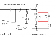
Hey all - quick question about the output stage in the schematic.
I'm using some fairly large output caps, so am going to mount them off board, and solder the 100ohm and 47k ohm resistors directly to the rca sockets. I need to make sure I'm tapping the correct point on the board.
However, when looking at the PCB itself, it seems that the 10uf output cap is actually after the 100ohm resistor, not before. Is there a mistake in the schematic, or the board?
I've attached an image of the schematic, highlighting the section.
Attachments
these two are in series, irrelevant which one go first
correct point on the board you're looking for - trace connected to drain of lower jFet
correct point on the board you're looking for - trace connected to drain of lower jFet
In that case, the 100r resistor can be mounted on the board, and just the cap, and 47k resistor off board.
See post #369. Pull the 47K resistor off the board and put it on the output jack. Bypass the coupling cap with a jumper. Connect one end of the coupling cap to the board and the other to the output jack.Mounting the cap and the resistor worked for me.
Last edited:
- Home
- Amplifiers
- Pass Labs
- DIY biamp 6-24 crossover