Not something i could answer without looking it up. My speakers all have the drivers within less than a quarter wavelength at the XO so essentially coincident.
dave
dave
what's the best strategy for adjusting the filters?
I recently finished my 6-24 and it was an enjoyable, intermediate level kit building experience. I made a component value mistake that led to an interesting debugging adventure but had no other drama. I worked out a why to use REW to graph the filter response so I can see the results of adjustments, and I'm wondering what are good approaches to adjusting the controls.
I'm starting with the 24 dB option so there are four trimmers per filter. There can be several ways to get the same -6 dB result so I'm wondering if one combination of values would give better results then the others. What's a good strategy for finding the best settings?
Personally I like to start with simple 6 dB/oct filters on a new speaker (played gently!)
and graduate in complexity to higher orders.
One of the points of this crossover is the independent adjustment of each pole.
Allows my favorite procedure: Research through wandering around....
and graduate in complexity to higher orders.
One of the points of this crossover is the independent adjustment of each pole.
Allows my favorite procedure: Research through wandering around....
>Research through wandering around....
I like that. I planed to start my wandering with clues from an existing crossover. I just bought refurbished RP-600ms and I tried bi-amping them with the ACA for the horn tweeters. So far I like where it's going. That led me to the 6-24.
Starting simple is a good suggestion and it's easy to try.
I like that. I planed to start my wandering with clues from an existing crossover. I just bought refurbished RP-600ms and I tried bi-amping them with the ACA for the horn tweeters. So far I like where it's going. That led me to the 6-24.
Starting simple is a good suggestion and it's easy to try.
In Palo Alto there are lots of stories about Bill and Dave practicing "management by walking around". I bet you could find them using internet search engines.
Just ordered the kit from the DIY-Store. Is there way to modify this to use balanced input and outputs instead of RCA connectors?
Appreciate any feedback.
Appreciate any feedback.
You can add an impedance balanced output. If you want differential in- and output, that will mean a longer signal path. As the crossover use to be near the source, there is not much that speak for a differential input.
Thanks.
I have couple of amps that use balanced inputs only. Preamp has both unbalanced (RCA) and balanced (XLR). So, at least, I need to convert unbalanced output of 6-24 Crossover to balanced. Will something like this work without disrupting the audio quality?
Balanced Line Driver & Receiver
Thanks
I have couple of amps that use balanced inputs only. Preamp has both unbalanced (RCA) and balanced (XLR). So, at least, I need to convert unbalanced output of 6-24 Crossover to balanced. Will something like this work without disrupting the audio quality?
Balanced Line Driver & Receiver
Thanks
I need to convert unbalanced output of 6-24 Crossover to balanced.
One simple way of doing this is with a transformer:
https://audioxpress.com/files/attachment/2685
I use a transformer volume control (passive preamp) between a non-balanced output of the phono preamp and a balanced input of the power amp. It works great.
Last edited:
to PC997
There are different possibilities to convert an unbalanced signal into a balanced one
active - by the use of OPAmps (like you linked to the ESP-site)
-THAT1646 could be worth a think
passive - with an output transformer?
The PA-people use DI-boxes (active or passive).....?
Only some thoughts....😕 How it sounds????
I only can say that the 6-24XO in single ended sounds great! In my system.
Greets
Dirk
Thank you Safesphere and Cubicincher. I will explore both and provide feedback when I complete.
Thanks.
I have couple of amps that use balanced inputs only. Preamp has both unbalanced (RCA) and balanced (XLR). So, at least, I need to convert unbalanced output of 6-24 Crossover to balanced. Will something like this work without disrupting the audio quality?
Balanced Line Driver & Receiver
Thanks
Good info, thanks for posting.
I have used the method shown in figure 4.
Nelson suggested about 75 ohm in addition to the output resistor to compensate for the output impedance of the jfet.
You can connect a non-balanced signal to a differential input. You can also follow Jensen's idea of adding a balanced output. You will need to use a suitable resistor for "X". It should match the output impedance of the crossover. I think it is about 200 Ohms. Balanced means the impedance of the two paths in the cable are the same.

Attachments
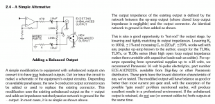
You can connect a non-balanced signal to a differential input. You can also follow Jensen's idea of adding a balanced output. You will need to use a suitable resistor for "X". It should match the output impedance of the crossover. I think it is about 200 Ohms. Balanced means the impedance of the two paths in the cable are the same.
Dropbox - adding a balanced output.jpg - Simplify your life
Dropbox - adding a balanced output.jpg - Simplify your life
to RogerGustavsson
Thanks for that information! I've learned something. And it can be so simple....
Greets
Dirk
Thanks for that information! I've learned something. And it can be so simple....
Greets
Dirk
You can connect a non-balanced signal to a differential input. You can also follow Jensen's idea of adding a balanced output. You will need to use a suitable resistor for "X". It should match the output impedance of the crossover. I think it is about 200 Ohms. Balanced means the impedance of the two paths in the cable are the same.
Dropbox - adding a balanced output.jpg - Simplify your life
Great information. Thank you very much for the guidance.
Good info, thanks for posting.
I have used the method shown in figure 4.
Nelson suggested about 75 ohm in addition to the output resistor to compensate for the output impedance of the jfet.
Pixelpusher,
Do you mean you used the method shown in Figure 1 - Balanced Line Transmitter? Figure-4 is the graph!
Attachments
Sorry, I posted the wrong reference. The article I was referring to is:
https://audioxpress.com/files/attachment/2685
It is figure 4 on page two. Simply adding a resistor to ground to match the output impedance of the positive signal.
https://audioxpress.com/files/attachment/2685
It is figure 4 on page two. Simply adding a resistor to ground to match the output impedance of the positive signal.
There is adding a balanced in or out connectors to a single-ended circuit (either passively or active), but for truly balanced you use twice as many boards, 1 set for the plus phase, 1 for the negative phase.
dave
dave
- Home
- Amplifiers
- Pass Labs
- DIY biamp 6-24 crossover