Using matched LSK170/LSJ74 instead
I have been a member on the forum for 16 years now, and this is my very first post - I was always just silently reading and learning from really fascinating discussions. The very fact that Nelson Pass actively participates here is just unbelievable. Thank you so much!
Back to the point: Would there be a worthwhile benefit of using a matched LSK170/LSJ74 instead of pairs of J113 in this active crossover?
This would require balanced power supply and some changes to the board. But I guess it would mean one could skip the DC blocking caps?
to Hazim #281
Hello Hazim,
you want to change this single-ended design into a complementary design.
If you set Vref to 0V and ground to your expected -V rails...😕
Change the buffers from single ended J113 + CCS (J113) to complementary
LSK170/LSJ74.
If you feed the PSU section with (for example 48V) and use 63V caps in the CRC -filter and in the Voltage divider. Mid of the voltage divider would be your ground. But audio ground of inputs and outputs??? Would have to be connected to Vref (= ground).
Could be possible? I have to think about it. Where is my schematic....🙄
Why do you want to change it to a complementary design? Do you need much more voltage swing?
If it is because of the sound? I would say: built it as it is designed - listen -
and I think you will have a wow-effect! 😀
😀
Greets
Dirk
Hello Hazim,
you want to change this single-ended design into a complementary design.
If you set Vref to 0V and ground to your expected -V rails...😕
Change the buffers from single ended J113 + CCS (J113) to complementary
LSK170/LSJ74.
If you feed the PSU section with (for example 48V) and use 63V caps in the CRC -filter and in the Voltage divider. Mid of the voltage divider would be your ground. But audio ground of inputs and outputs??? Would have to be connected to Vref (= ground).
Could be possible? I have to think about it. Where is my schematic....🙄
Why do you want to change it to a complementary design? Do you need much more voltage swing?
If it is because of the sound? I would say: built it as it is designed - listen -
and I think you will have a wow-effect!
😀Greets
Dirk
6-24XO experience
Hello members,
last night I changed the Preamp in my setup:
Preamp: Waynes BAF2018 linestage
Active crossover: 6-24XO (for sure🙄)
High channel amp: M2X
Low channel amp: 50W-SE-Schade
I had to readjust the volume pots on the 6-24XO and I was inverting
the polarity of the mid/tweeter at the outputs of the M2X.
Filter settings are great. I made minimal adjustments at the trimpots of the high pass filter).
I think the greatest benefit to go active is the increased control of the amp to the speaker. The amps have to reproduce a limited frequency range and they do not 'see' the complex load of an passive crossover.
The increase in audible details is evident.
You hear a string of an instrument swinging out that clearly - fantastic!
You hear small little things happening in the background of the music.
This XO is a real pleasure! 😀
Thanks!
Dirk
6-24XO experience
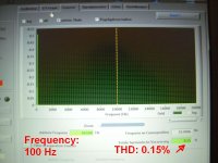
And I made a few 'fast and dirty' measurements with the 6-24XO last night.
I only used my old laptop with an oscilloscope software and measured the
THD in the low-pass. Not that I don't believe the measurements of Mr.Pass!
And I don't have an AP - or HP- or Rohde+Schwarz- Distortion- Analyzer!
But I've got also pretty low THD.
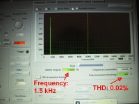
With a sinuswave at an level of 0.5 V fed into the 6-24XO:
At 100 Hz: around 0.15% ( I think influenced by the double of the 50 Hz mains?)
At 1.5 kHz: around 0.02 %
Really good!
Sorry for the bad pics. Screenshot didn`t work!?
Greets
Dirk
And I made a few 'fast and dirty' measurements with the 6-24XO last night.
I only used my old laptop with an oscilloscope software and measured the
THD in the low-pass. Not that I don't believe the measurements of Mr.Pass!
And I don't have an AP - or HP- or Rohde+Schwarz- Distortion- Analyzer!
But I've got also pretty low THD.
With a sinuswave at an level of 0.5 V fed into the 6-24XO:
At 100 Hz: around 0.15% ( I think influenced by the double of the 50 Hz mains?)
At 1.5 kHz: around 0.02 %
Really good!
Sorry for the bad pics. Screenshot didn`t work!?
Greets
Dirk
Attachments
Why do you want to change it to a complementary design? Do you need much more voltage swing?
If it is because of the sound? I would say: built it as it is designed - listen -
and I think you will have a wow-effect!
Greets
Dirk
I think he want to skip the CD-blocking caps which are electrolytics in the BOM.
But I guess it would mean one could skip the DC blocking caps?
Is anyone planning on bringing the level controls out to their front panel, and if so, what are you going to use for a volume control? E-bay has stepped ladder attenuators (Valab) for a good price. Anyone tried these? Other suggestions?
Hi guys! Thanks a lot to Nelson: this is a fantastic gift!
My friend Mauro and I are building a 6-24 cross for a Pass SLOB with Lii Fast 8 and Eminence Beta15. Any suggestion for cross point and C values (maybe 68pF?) would be appreciated
My friend Mauro and I are building a 6-24 cross for a Pass SLOB with Lii Fast 8 and Eminence Beta15. Any suggestion for cross point and C values (maybe 68pF?) would be appreciated
+1 I also noticed the same thing. The schematic from Mr. Pass' paper it says 0.1 uf at the input of LF and HF but in the board layout marking it says 10uf. Wonder which one is right ? I"m thinking 0.1 uf is a better choice for DC blocking/bypass at the input not 10uf. It seems a bit too much
Thanks,
Tom
I'd try NOS Ero 1813 MKT 63V in that position (or at least new Vishay 1813) because they sound good to me and are very small in vertical position, bending one terminal.
Last edited:

The aim would be a cross freq @ 80-90 Hz for Beta and 120-150Hz for Lii. Is the value right?I'd try NOS Ero 1813 MKT 63V in that position (or at least new Vishay 1813) because they sound good to me and are very small in vertical position, bending one terminal.
Hi guys! Thanks a lot to Nelson: this is a fantastic gift!
My friend Mauro and I are building a 6-24 cross for a Pass SLOB with Lii Fast 8 and Eminence Beta15. Any suggestion for cross point and C values (maybe 68pF?) would be appreciated
It depends on what slopes you want. 68pF sounds very small. Maybe you mean 68nF?
As far as I get it:
High pass section 12dB/octave with R1 15kOhm and R2 30kOhm and all Cs 68nF will give about 110 Hz. Decreasing R1 to 10k and R2 to 20k will raise the cut-off frequency to about 170 Hz.
Low pass section 24 dB/octave with all Rs 15kOhm and C 2x68nF and C/2 68nF will be good for a start.
You will need to varify the response by measuring your speakers in situ.
Thank you so much for spending your time on this Nelson. Your support of this community is really just unbelievable.
Thanks.
Thanks.
Big order arriving here shortly, then off to store.
share the Fun
- Home
- Amplifiers
- Pass Labs
- DIY biamp 6-24 crossover