Hello robnik33,
Thank you for all details and advises. I go for Kp then.
I might presented what I see incorrectly to you.
When initial speed is bit high (right after system’s start), the correction is working very nice. I’m very close to the target speed for 5 min. Then, and after about 5-6 min, when motor is already warm, speed is intending to go bit down and no correction till it’s reaching 33.311. Then algo kicks in with pulses. However, these pulses are stops when speed is equal to about 33.320. It can submit one or two more pulses to get it closer to 33.333, but it is not happening and it is stays there. It would be nice to have same response from both directions: when it’s going from High to the target and when it is going from LOW to the target. That is my fight now.
robnik33 hit on a key point: The minimum step for speed change is 0.01Hz which will limit the resolution of the target speed. This project was never intended for automatic adjustment; if it was, I would have used a different scheme to increase the resolution (the Eagle/Falcon & now SOTA Condor has a frequency resolution that is 18x finer or 1/1800 Hz). The frequency resolution of the SG4 was kept the same as the VPI SDS so that manual adjustment would not take forever to arrive at a target speed.
That being said, it was quite an accomplishment to get the auto correct to work as well as it does on your system. Good work robnik33!
Bill, thanks for all your help and kind words. If you ever decide (or are allowed) to build an integrated controller + tach, I'd love to build one!
Alexkosha,
Your comment on asymmetrical behavior prompted me to go thru the code again and I spotted an error in how I rounded the absolute error to m, the number of button pushes.
Instead of this as now:
ADJFREQ = PIDOUT * 200 / 3 + 0.5; //* amount of frequency adjustment needed in 0.01 Hz (# button pushes, + 0.5 offset)
m = abs(int(ADJFREQ)); //* number of button pushes
Try this:
ADJFREQ = PIDOUT * 200 / 3; //* amount of frequency adjustment needed in 0.01 Hz
m = int(abs(ADJFREQ)+0.5); //* integer number of button pushes, offset by 0.5
The earlier rounding was not symmetric, potentially giving a different result if the absolute error was positive or negative. I am testing it now, it does seem a bit "jumpier" with the stylus down. You may need to adjust the PID parameters as well.
I see. I’ll test it tonight too. Let us know your findings for new PIDs. Thank you a lot for such dedication and knowledge share.
Alex
Alex
It works better now and symmetry is definitely improved. Please let me know your new PID parameters (if you changed any). I’ll continue my observation and let you know. So far, I’m happy and can leave my PID as is.
Alex,
I think the current PID parameters are ok. With the fix, I am now seeing more corrections in the first minute or two, which I think is just the Lenco motor stabilizing. I'm glad it is working for you!
Robert
I think the current PID parameters are ok. With the fix, I am now seeing more corrections in the first minute or two, which I think is just the Lenco motor stabilizing. I'm glad it is working for you!
Robert
Hi Robert, I totally forgot to ask you... Is any way to add total rotation count to the code and to preset it on display? I know it can be stored on eprom, but can’t be erased/reset without code reload to arduino. That feature might be useful for tracking platter bearings periodical maintenance.
Alex,
That would be a cool feature. Not sure I'd get to it anytime soon, maybe someone else can give it a try?
That would be a cool feature. Not sure I'd get to it anytime soon, maybe someone else can give it a try?
Robert, no one close to me has that talent to set that code that nicely. I hope you can get to that project soon. I guess that this thread community will be very appositive to have that feature available.
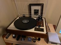
I'm not completely sure this is the correct thread to post in, but I have recently completed installation of Steve's Zeus controller into a Linn LP12. I bought the fully assembled version so it was a piece of cake. The instruction manual is amazing. Better than any commercial document and even more so for DIY stuff! I am very pleased with the operation of the controller. It quickly brings the table to correct speed and keeps it rock solid. I will eventually test with my Kenwood wow & flutter meter, but using a separate tachometer, I'm getting fluctuation of about 0.006%.
I highly recommend this controller. Hopefully there will be another group buy!
I highly recommend this controller. Hopefully there will be another group buy!
Attachments
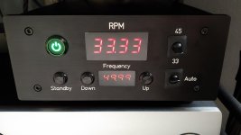
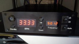
Finally finished my combined tachometer and SG4 motor controller! Got the front panel back from Front Panel Express. The enclosure I used was overkill with heatsinking, but it sure was nice to have an 8mm thick front panel that I could countersink 3mm acrylic for the displays.
It runs cool and works great managing speed. Thanks again to Bill and others who contributed time and code.
Anyone want to tackle adding a stylus timer?
I have also attached the latest code (Tach_7Seg_R7) consolidating changes covered in various posts.
It runs cool and works great managing speed. Thanks again to Bill and others who contributed time and code.
Anyone want to tackle adding a stylus timer?
I have also attached the latest code (Tach_7Seg_R7) consolidating changes covered in various posts.
Attachments
I'm not completely sure this is the correct thread to post in, but I have recently completed installation of Steve's Zeus controller into a Linn LP12. I bought the fully assembled version so it was a piece of cake. The instruction manual is amazing. Better than any commercial document and even more so for DIY stuff! I am very pleased with the operation of the controller. It quickly brings the table to correct speed and keeps it rock solid. I will eventually test with my Kenwood wow & flutter meter, but using a separate tachometer, I'm getting fluctuation of about 0.006%.
I highly recommend this controller. Hopefully there will be another group buy!
It is not right thread. Steve opened dedicated thread for Zeus controller.
Hi Robert,
It seem that Kp less than 1 turns PID off. I see no action when I set Kp to 0.8. So, 1 is min for Kp. Correct?
Alex
It seem that Kp less than 1 turns PID off. I see no action when I set Kp to 0.8. So, 1 is min for Kp. Correct?
Alex
Alex,
Kp is the current error, the difference in the current speed and the desired speed setpoint (33.3/45). So Kp at 0.8 takes 80% of this value as the proportional correction term. In general, the smaller the value the longer time it will take to reach the setpoint. Values above 1 may cause overshoot or oscillation because you are correcting more than the current error. For my Lenco, I am using int kp = 1, ki = 0.6, kd = 0.4. I've been running this for months and it is working great.
The thing about PID tuning is all systems will react differently. In general, try values of 1 or less for all three.
What turntable are you using and what are your values for Ki and Kd when you are getting no response with Kp=0.8?
Hi Robert,
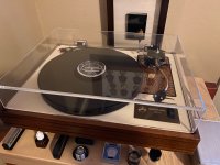
My TT is Conrad Johnson Sonographe SG-3. I fully rebuilt it and Premotec 31813 motor replaced old Hurst. I use kp = 1, ki = 0.4, kd = 0.2 now. It is Ok, but I see some overshoot time to time. I assumed that 0.9 or 0.8 for Kp might help.
My TT is Conrad Johnson Sonographe SG-3. I fully rebuilt it and Premotec 31813 motor replaced old Hurst. I use kp = 1, ki = 0.4, kd = 0.2 now. It is Ok, but I see some overshoot time to time. I assumed that 0.9 or 0.8 for Kp might help.
Attachments
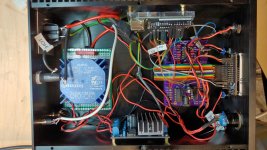
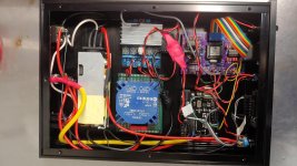
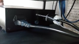
So I decided to build a second unit and refined the physical design a bit more. I stripped the covers off and built the power supply into the chassis so now I have an IEC connector for input power. The rest of the internals are the same. The case is slimmer with no unnecessary heat sinking. I used Front Panel Express again for a professional look.
Attachments
Excellent implementation. I wish to have company near me witch can be dealing with front panels millings. I use local machine shop and they are doing an excellent cuts, but quite pricey ($80 per hour).
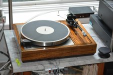
Here is my box attached.
Question to Robert.
Does PID can deal with 20/27Hz setup (instead of 60/81) ? I can’t find any line in code limiting PID initial frequency in Tacho. I’m finalizing setup with DC motor connected to full set from Pyramid devices with same SG4. So far, can’t get any luck with PID that it is not working there. My motor is getting to 300RPM with 19.50Hz. That speed is delivers 33.333 to my sub-platter and platter.
Please let me know.
Attachments

Last edited:
It's funny, choosing switches took the most time!
Lighted power switch, 19mm
19mm push button switch black press button Led power mark lamp button latching | eBay
Black toggle switch, 15mm
5Pcs SCI R13-402 Round 2Pin ON-OFF SPST 2Position Toggle Switch 3A 250VAC | eBay
Momentary on switches, 12mm
12mm Waterproof Flat Stainless Steel Momentary Power Push Button Switch Black | eBay
Note that these are very small, tip of the finger to engage, also took months to arrive from China. Used in 2nd build.
These below are easier to engage as the whole button protrudes, used in first build (see side-by-side photo)
https://www.amazon.com/dp/B01G821G6A?ref=ppx_pop_mob_ap_share
Also Alex, Front Panel Express has an app you download to design and order your panel online. Cost was around $80, each panel took about a week. They are located in Kent, WA
- Home
- Source & Line
- Analogue Source
- Digital Tachometer for record player (LCD display)