Hi Robert,
It is working now!!! I replaced SG4 with my spare one and all is totally fine now with same original code for 20Hz. My original SG4 has some issue and I’ll troubleshoot it later.
One step is remained and it is PID parameters fine tuning.
My deepest appreciation for your knowledge, goodwill and dedication. I’m very happy with test results.
Now, it is very close and alternative replacement for Sota Condor (former Falcon) and Roadrunner combo. Pyramid created exceptional projects for DYI community. It is fun to assemble and very useful staff.
Alex, glad it worked out. After I got over confusing RPM and Hz, I couldn't see anything in the code that would cause a problem.
And I totally agree that Pyramid (Bill) does great work and is very gracious to share!
And I totally agree that Pyramid (Bill) does great work and is very gracious to share!
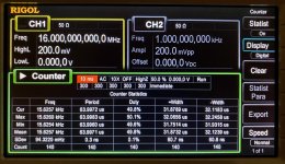
Images for PB2 freq. measured on my Arduino Uno PIN #2. It is not an Italian made unit. My board is made in China and purchased from eBay.
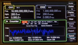
So, it is relatively stable during first 3-4 min, and then it starts to dance quite significantly. Please see video taken after about 10 min of warming time.
November 22, 2020 - YouTube
So, it is relatively stable during first 3-4 min, and then it starts to dance quite significantly. Please see video taken after about 10 min of warming time.
November 22, 2020 - YouTube
Attachments
Last edited by a moderator:
Why did I posted these images and video? So, I troubleshooted my case when I had some delta (-0.030) with RPM readings between our Arduino Roadrunner and some alternative tacho based on different principals. I consulted with Pyramid and he quickly helped me to find the reason. Straight to the end: 15.625kHz is translated to 1875000 in code for:
onst float CALIBRATE = 1873440; //*equals freq @ PB2 x 120
As you see, I had 1873440 in my sketch and that was too off. Have no delta with 1875000.
onst float CALIBRATE = 1873440; //*equals freq @ PB2 x 120
As you see, I had 1873440 in my sketch and that was too off. Have no delta with 1875000.
Alex, I am googling to try out your code. Is there a recommended magnet? I have a sensor and a mechanism to attach it to my plinth.
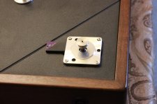
Not sure if I got your question. First of all, it is not my code (sketch). It was created and finalized by many members here, and we just added some final touches to it. BTW, these “final touches” are fine for my setup and might not applicable for other members setups. Magnet type and size mentioned by Pyramid in relevant thread and I use 5x1mm N52 Neodymium magnet with Pyramid’s Hall Effect Sensor. I purchased magnet from eBay.
Wholesale Tiny Block Round Disc Ring Hole Rare Earth Neodymium Magnets N52 Grade | eBay
Wholesale Tiny Block Round Disc Ring Hole Rare Earth Neodymium Magnets N52 Grade | eBay
Last edited:
Not sure if I got your question. First of all, it is not my code (sketch). It was created and finalized by many members here, and we just added some final touches to it. BTW, these “final touches” are fine for my setup and might not applicable for other members setups. Magnet type and size mentioned by Pyramid in relevant thread and I use 5x1mm N52 Neodymium magnet with Pyramid’s Hall Effect Sensor. I purchased magnet from eBay.
Wholesale Tiny Block Round Disc Ring Hole Rare Earth Neodymium Magnets N52 Grade | eBay
Thanks! As it turns out I have some N35 magnets from a woodworking project. Perhaps give those a try first, or has the lower pull been shown not to work?
You know, it is strength and also distance play a role there. So, try utilize these N35 and see if signal is triggered. Orientation of magnet is also important. I place my magnet about 4-5 mm from sensor and it works totally fine. I also have another turntable with mentioned above optical sensor and no issues with these sensors either. My personal preference is Hall Effect sensor since it is more thin and seems more elegant.
Question, made a tacho with the arduino code from here and an optical sensor.
My tt (VPI Prime) came with the hall sensor from a roadrunner, would it work if plugged instead of the optical sensor or it needs a different programing? Dont have the magnet so to just test...
Regards
My tt (VPI Prime) came with the hall sensor from a roadrunner, would it work if plugged instead of the optical sensor or it needs a different programing? Dont have the magnet so to just test...
Regards
I use Roadrunner sensor too and same sketch is serves both. You just need to verify wiring of sensor to Arduino. I believe it is some drowning here in thread.
Thanks, if I find a magnet Ill post the results.I use Roadrunner sensor too and same sketch is serves both. You just need to verify wiring of sensor to Arduino. I believe it is some drowning here in thread.
Dear all,
I am using a very old sketch for my Arduino tach.
Would really like to try the auto-correct function shared here.
As I am really not a programming person, do you think you could watch at my sketch and help me edit it with the auto-correct function.
Would appreciate it big time.
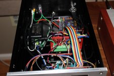
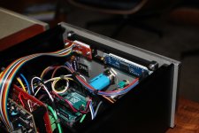
The hardware mod already implemented just can't figure out what to change in the .ino file.
I am using a liquid crystal I2C display 16x2 and obstacle avoidance sensor.
Thank you big time in advance.
Best
Orlin
I am using a very old sketch for my Arduino tach.
Would really like to try the auto-correct function shared here.
As I am really not a programming person, do you think you could watch at my sketch and help me edit it with the auto-correct function.
Would appreciate it big time.
The hardware mod already implemented just can't figure out what to change in the .ino file.
I am using a liquid crystal I2C display 16x2 and obstacle avoidance sensor.
Thank you big time in advance.
Best
Orlin
Attachments
Last edited:
Working on implementing the auto correct along with the BLWS231S-24-2000 BLDC motor, so I am running much lower frequencies (~19.6X hz @ 33.333). Couple questions:
1 - Anyone have any different PID tuning values? I have it working with the values in the base sketch (kp = 1, ki = 0.6, kd = 0.4), but it quickly starts to over-correct with these. In my setup, it should only be tweaking +/- 0.01 hz every few mins to adjust for any drift as things warm up, etc.
2 - After I implemented the sketch with the auto correct, my encoder on my SG4 no longer works for up/down. Standby still works. Buttons on the SG4 board still work. Not sure if sending the 5V with "digitalWrite(UP, HIGH);" to the up/down pins hurt it? Is there a way to change that to "not LOW"?
Regarding #2 (obvious Arduino noob, but I'm learning), I did not have any resistors between the Arduino and the SG4/Encoder. So with the UP/DOWN held at 5V on Arduino, when I was turning the encoder it was shorting that UP/Down assigned pins. When I pull the cables from the arduino pins, the encorder works again with the SG4. Now the tach pin does not work either as it is also stuck in an indeterminate ~3-4V. Lesson learned (I Think). ordered another arduino, will add resistors between everything.
I did eventually get everything working. Will probably write some different code for the Auto adjustment as with the BLWS motor every .01 Hz adjustment is about .015 rpm, so i think I just want it to adjust for long term drift (i.e., up or down .01-.02 Hz over a listening session.) based on an average reading.
Attachments
-
 IMG_7871 (Large).JPG341.4 KB · Views: 301
 -
 IMG_7875 (Large).JPG297.1 KB · Views: 506
 -
 IMG_7882 (Large).JPG294.4 KB · Views: 504
 -
 IMG_7881 (Large).JPG271.9 KB · Views: 508
 -
 IMG_7878 (Large).JPG364.2 KB · Views: 517
 -
 IMG_7876 (Large).JPG266.3 KB · Views: 515
 -
 IMG_7884 (Large).JPG322.4 KB · Views: 334
 -
 IMG_7885 (Large).JPG327.3 KB · Views: 299
Working on implementing the auto correct along with the BLWS231S-24-2000 BLDC motor, so I am running much lower frequencies (~19.6X hz @ 33.333). Couple questions:
Not sure if sending the 5V with "digitalWrite(UP, HIGH);" to the up/down pins hurt it? Is there a way to change that to "not LOW"?
Why not just connect the Arduino to the other side of the resistor on the up/down buttons and send “low”?
That first question really was my not understanding the whole thing at the time. I missed the code if keeping those pins high and pulsing low. So you can connect it to the buttons on the SG4, but I did need the resistors between the Arduino and the encoder chip otherwise the encoder was always held high on up/down and did not work.
- Home
- Source & Line
- Analogue Source
- Digital Tachometer for record player (LCD display)