Trigger(3) and PIDactive(5)
Not sure to what points on the SG4 module(?) these are connected to.
I'm wildly guessing Arduino pin numbers, and the sensor is a Hall effect part?
Thanks!
I updated your diagram for phase-shift split motor run setup.
Also, have an error on your sketch during "Verify" (please see attached). What Arduino board is used there? I have Uno.
I believe I must update you PID sketch for my type of display. Can you please help me to mod it? I can send you my sketch.
Not sure to what points on the SG4 module(?) these are connected to.
I'm wildly guessing Arduino pin numbers, and the sensor is a Hall effect part?
Thanks!
Is there a specific debounce time for the Standby button? I can control Up and Down others quite well with 60 ms delay between LOW to HIGH and 30 ms afterwards. I'm finding it hard to reliably take things out of Standby at the start of my program though, I see it flash out of Standby and then return back quickly. I'm wondering if there is a settle time I need to respect?
Is there a specific debounce time for the Standby button? I can control Up and Down others quite well with 60 ms delay between LOW to HIGH and 30 ms afterwards. I'm finding it hard to reliably take things out of Standby at the start of my program though, I see it flash out of Standby and then return back quickly. I'm wondering if there is a settle time I need to respect?
What exactly are you doing? Does your Arduino tach take the SG4 out of Standby and if so, why?
When the SG4 exits standby, it does a soft_start where it ramps the amplitude of the sinewaves from zero to maximum over a period of ~650mS, which also acts as a debounce time. After that, it clears any keypress flags and looks to see if Standby is pressed; if it is, it goes back to standby.
Yes, it takes it out of Standby because I have repurposed a button on my motor pod to start things up. I think this will help, thanks!
Would anyone here be interested in doing a bit of testing on a SG-4/MA-3D companion board? I have most of the software complete, minus a few extras that others might not care about (12v trigger, etc.) and an extra PCB or two. I would want another pair of eyes here and there, would definitely be a low key commitment ..
This thread happened to catch my attention while cruising around and thought the LCD panel was an interesting idea for a TT motor.
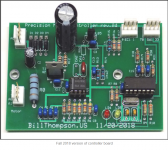
As I was reading through it, I found that you folks were working on a motor controller being programmed via an Arduino. I have a TT motor/controller that was developed by a gentleman by the name of Bill Thompson. He is a very nice guy and also the found of Ashley home audio (since retired). So looking at what you folks are doing and what Bill designed and has in the open domain I thought I would show you guys a few things from his webpage and also put the links here in case some of his coding (Microchip PicKit 3) could be of some use to you folks.
So first off everything I post below was from Bill and not myself (just want to make sure of his credit). Also below is the link to his page where he discuss' the motor controller and such. I hope this is in someway helpful/usefull.
Turntable DC Motor System – BillThompson.us
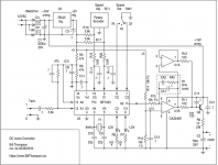
"My goal was perfect speed stability and no audible motor noise. The approach is simple in concept; the tachometer on the motor fires a one-shot with a fixed pulse width. This pulse is fed to an integrator the output of which drives the motor. When the duty cycle is less than 50% (slow) the integrator ramps up raising the motor voltage and speeding it up. If the duty cycle exceeds 50% (fast) the integrator ramps down lowering the motor voltage and slowing it down. The system reaches stability when the duty cycle of the pulse is exactly 50%.
The first version of this controller was completely analog using a 555 timer for the one-shot and this worked very well. However it required high quality resistors and capacitors for the one-shot timing and the variations in individual 555 chips made re-calibration necessary upon replacing chips.
In the current version of the motor controller the 555 timer has been replaced by a PIC microcontroller for the one-shot. This opens a whole new range of possibilities. The time base is an 8 mHz. crystal and the speed adjustment is accomplished by the encoder. Whenever an adjustment is made the new timing information is stored in an EEPROM in the PIC chip so the speed settings are remembered when powered off. A purist might have taken the time to replace the analog integrator and output transistor with something digital as well but the motor takes so little power to run and the analog output works so well that I didn’t bother.
I did several updates to the hardware and software in the Fall of 2018. The 16F1823 has a nice built-in comparator which the tachometer can drive directly. I now use that rather than the external comparator that was a holdover from the analog controller design. This left me with an unused opamp section in the dual opamp so I used that as a “current doubler” driving the pass transistor. I also did a bunch of work on the rotary encoder software. Encoders can be noisy and sometimes give sporadic false readings. A combination of software de-bouncing and input hysteresis makes the encoder much smoother.
The hex file can be used to program a 16F1823 controller chip using a Microchip PicKit 3 programmer or equivalent.
My motor pulley is a little larger than the one on the original motor and I always run the turntable’s own speed selector at 78 RPM and set the motor speed to get the rotational speed I want, usually 33.33 RPM. This lets the motor run very slowly, about 600 RPM, lowering the motor vibration frequency from the original 30 Hz. to about 10 Hz. and this is much easier to deal with. With a little gentle filtering the turntable contributes no significant L.F. noise at all.”"
Some of the source code:
Motor Control Source Code – BillThompson.us
;------------------------------------------------------
;conditional options
;#define rampup ;comment this out to disable ramp-up
#define mhz8 ;comment this out to use 4mhHz xtal
;------------------------------------------------------------
; PORT bit definitions
; port A
;tach0 RA0 ;+ input from tachometer
;tach1 RA1 ;- input from tachometer
;gpout RA2 ;output to integrator
; port C
;gp78 RC2 ;low for 78 speed
;gp33 RC3 ;low for 33 speed
;both high for 45 speed
;encode RC0-1 ;rotary encoder bits
;speed sel RC2-3
;avail RC4-5 ;available
As I was reading through it, I found that you folks were working on a motor controller being programmed via an Arduino. I have a TT motor/controller that was developed by a gentleman by the name of Bill Thompson. He is a very nice guy and also the found of Ashley home audio (since retired). So looking at what you folks are doing and what Bill designed and has in the open domain I thought I would show you guys a few things from his webpage and also put the links here in case some of his coding (Microchip PicKit 3) could be of some use to you folks.
So first off everything I post below was from Bill and not myself (just want to make sure of his credit). Also below is the link to his page where he discuss' the motor controller and such. I hope this is in someway helpful/usefull.
Turntable DC Motor System – BillThompson.us
"My goal was perfect speed stability and no audible motor noise. The approach is simple in concept; the tachometer on the motor fires a one-shot with a fixed pulse width. This pulse is fed to an integrator the output of which drives the motor. When the duty cycle is less than 50% (slow) the integrator ramps up raising the motor voltage and speeding it up. If the duty cycle exceeds 50% (fast) the integrator ramps down lowering the motor voltage and slowing it down. The system reaches stability when the duty cycle of the pulse is exactly 50%.
The first version of this controller was completely analog using a 555 timer for the one-shot and this worked very well. However it required high quality resistors and capacitors for the one-shot timing and the variations in individual 555 chips made re-calibration necessary upon replacing chips.
In the current version of the motor controller the 555 timer has been replaced by a PIC microcontroller for the one-shot. This opens a whole new range of possibilities. The time base is an 8 mHz. crystal and the speed adjustment is accomplished by the encoder. Whenever an adjustment is made the new timing information is stored in an EEPROM in the PIC chip so the speed settings are remembered when powered off. A purist might have taken the time to replace the analog integrator and output transistor with something digital as well but the motor takes so little power to run and the analog output works so well that I didn’t bother.
I did several updates to the hardware and software in the Fall of 2018. The 16F1823 has a nice built-in comparator which the tachometer can drive directly. I now use that rather than the external comparator that was a holdover from the analog controller design. This left me with an unused opamp section in the dual opamp so I used that as a “current doubler” driving the pass transistor. I also did a bunch of work on the rotary encoder software. Encoders can be noisy and sometimes give sporadic false readings. A combination of software de-bouncing and input hysteresis makes the encoder much smoother.
The hex file can be used to program a 16F1823 controller chip using a Microchip PicKit 3 programmer or equivalent.
My motor pulley is a little larger than the one on the original motor and I always run the turntable’s own speed selector at 78 RPM and set the motor speed to get the rotational speed I want, usually 33.33 RPM. This lets the motor run very slowly, about 600 RPM, lowering the motor vibration frequency from the original 30 Hz. to about 10 Hz. and this is much easier to deal with. With a little gentle filtering the turntable contributes no significant L.F. noise at all.”"
Some of the source code:
Motor Control Source Code – BillThompson.us
;------------------------------------------------------
;conditional options
;#define rampup ;comment this out to disable ramp-up
#define mhz8 ;comment this out to use 4mhHz xtal
;------------------------------------------------------------
; PORT bit definitions
; port A
;tach0 RA0 ;+ input from tachometer
;tach1 RA1 ;- input from tachometer
;gpout RA2 ;output to integrator
; port C
;gp78 RC2 ;low for 78 speed
;gp33 RC3 ;low for 33 speed
;both high for 45 speed
;encode RC0-1 ;rotary encoder bits
;speed sel RC2-3
;avail RC4-5 ;available
Attachments
luvdunhill,
If you are still looking for someone to collaborate with i would be a very willing partner.
I sent you a PM.
If you are still looking for someone to collaborate with i would be a very willing partner.
I sent you a PM.
128x32 OLED display
Hello,
Greggan posted earlier some code that uses a small OLED display, which I have and it works with his code, however trying to comment out the code for your display, and adding in Greggans display code results in compile errors.
Maybe you have an idea how to substitute the display in the code?
The CNY17 reflective IR-sensor works great with 1K on the IR-diode and 47K on the collector. Emitter and cathode to ground, 5V to the "other" end of the resistors. Emitter to pin3.
Thanks!
60Hz setup with that correction is working flawlessly.
**I did set it with 60Hz:
ADJFREQ = PIDOUT * 180; //* amount of frequency adjustment needed in 0.01 Hz
SG4 with PID - YouTube
Hello,
Greggan posted earlier some code that uses a small OLED display, which I have and it works with his code, however trying to comment out the code for your display, and adding in Greggans display code results in compile errors.
Maybe you have an idea how to substitute the display in the code?
The CNY17 reflective IR-sensor works great with 1K on the IR-diode and 47K on the collector. Emitter and cathode to ground, 5V to the "other" end of the resistors. Emitter to pin3.
Thanks!
update
I did find out how to substitute the display with a very small OLED 128x32, after some trials and errors.
The Tachometer with a feedback to the SG-4 is working OK. Thanks all! 😎
Using Hall sensors with added unbalanced mass of magnets, and the less than snappy output response, and alternating magnetic fields around the MC cartridge for these does not appeal to me.
The optical reflective IR sensors works OK, and will have a Schmitt buffer added to square up the sensor output.
With the Tacho, accuracy is moved from the SG-4 with its 10ppm crystal to the one on the Arduino Nano with less precision. A low jitter 16MHz TCXO are not that expensive, but the inaccuracy of the Nano clock CSTCE16M0V53-R0 may be swamped by other timing errors.
The low feedback frequency (1 per rev.) does not seem ideal, more would be better. Errors could be averaged out, and/or more frequent feedback.
Faster processor are as low cost as the Nano, and could include more features, like an ESP32 with performance output via Bluetooth to your smartphone. A smartphone app could analyze the speed stability and graph it like the many RPM apps available. (Putting a smartphone on the platter adds uncertainty as it may not be perfectly balanced.)
Would not a variable speed be better with belt drive to minimize belt slippage during start and stop?
The gradual amplitude rise during startup is ineffective as too low voltage just makes the motor buzz. Max torque is needed to start that mass.
the slope should be perhaps 4 seconds, at least on my 2.2kg platter.
Once the platter is at set speed, power could even be reduced, maybe take out one phase or reduce a voltage? Less motor power, less motor noise.
Last edited:
Using Hall sensors with added unbalanced mass of magnets, and the less than snappy output response, and alternating magnetic fields around the MC cartridge for these does not appeal to me.
The magnets are ~1/20 gram, far less than the VTF exerted by the stylus. At 33 RPM, they will exert negligible force on the bearing. Interference with a MC cart is only a problem with very thin and non-metalic platters.
The optical reflective IR sensors works OK, and will have a Schmitt buffer added to square up the sensor output.
The Hall sensor has a built in Schmitt trigger and creates a squarewave output. I originally used an optical sensor, but I found the rotating mirror to be a distraction.
With the Tacho, accuracy is moved from the SG-4 with its 10ppm crystal to the one on the Arduino Nano with less precision. A low jitter 16MHz TCXO are not that expensive, but the inaccuracy of the Nano clock CSTCE16M0V53-R0 may be swamped by other timing errors.
There shouldn't be any timing errors unless the number of instruction cycles needed to complete the construction of the waveform exceeds the interrupt interval. I don't know if this has been verified on the Nano app which is written in C, but in assembly language, it is not a problem.
The low feedback frequency (1 per rev.) does not seem ideal, more would be better. Errors could be averaged out, and/or more frequent feedback.
Faster processor are as low cost as the Nano, and could include more features, like an ESP32 with performance output via Bluetooth to your smartphone. A smartphone app could analyze the speed stability and graph it like the many RPM apps available. (Putting a smartphone on the platter adds uncertainty as it may not be perfectly balanced.)
Once per revolution has several advantages: The timing pulse will occur at precisely the same place every time, thus removing the need for precision machining and/or placement of multiple timing marks which could lead to increased W&F. It also moves the speed correction (if done correctly) down in frequency below the audible threshold.
A faster processor is not needed as long as all the needed tasks are completed within each interrupt cycle. Likewise, 32 bit processors aren't necessary for this limited application.
Would not a variable speed be better with belt drive to minimize belt slippage during start and stop?
The gradual amplitude rise during startup is ineffective as too low voltage just makes the motor buzz. Max torque is needed to start that mass.
the slope should be perhaps 4 seconds, at least on my 2.2kg platter.
Once the platter is at set speed, power could even be reduced, maybe take out one phase or reduce a voltage? Less motor power, less motor noise.
The amplitude ramping was done to prevent the output amps from going into overload at start up and triggering their over protection circuitry (shutting down), not to prevent belt burn out. AC synch motors have a limited speed range, most will not run at all below 30Hz or above 90Hz.
The Condor uses a 3 phase BLDC motor and does ramp the speed as you suggest, starting the platter at ~5 RPM and ramping up to 33/45/78 in a controlled manner. This requires the amplitude to be adjusted along with the speed to maintain torque at a constant level.
If you disable one phase of an AC synch motor, it won't run properly. Reducing the drive level after the platter has reached speed IS effective in reducing vibration and noise.
Thanks Pyramid,
Precision "machining" would not be needed for my Rega TT, a special disc under the subplatter would work. As only IR light is being used , a IR reflective surface is needed.
I designed a round 0.6mm PCB with multiple optical reflective surfaces (ENIG) that would fit, and the opto-coupler would be placed under it, thru a hole drilled in the plinth.
The PCB mfg process holds tight enough tolerances.
Once per rev may be enough though, but mechanically not a great challenge. Off-center drilled records are not uncommon and would swamp timing accuracy.
Using old near obsolete 8-bit processors may be good enough, but a modern 15x faster dual core lower cost processor gives opportunity for more features, like I stated.
ASM is undoubtedly superior to C in deterministic timing, but for a 0.5555 Hz process, nanosecond resolution may be unnecessary, and the ISR resolution may be sufficient in the ESP32, ARM, or some other micro controller running much faster. C compilers are getting better and the fatter MCUs have more overhead anyway making ASM less important.
32-bit is nice if you want to add fancy graphics or a BT interface. DSP for a 100 Hz max sine wave does not need a lot of bits.
32 bit ARM processors are cheap and you could easily use more than one if there would be a timing crunch servicing fancy features.
If you have some non-compete clauses with your TT projects I understand your reluctance for SW development in the public domain.
Thanks!
128x32 OLED display update
The feedback system works great. I'm using a CNY17 for reflective optical feedback via a Schmitt trigger buffer. The Arduino Nano clone has the .3% 16MHz resonator removed and a substituted with a ±1.5 ppm TCXO.
The ~ 3W motor is driven by a stereo Class-D amp capable of 20+W driving a couple of "Flathead" 6VA transformers.
The Hammond case is hastily put together, as this is a "prototype".
The rotary encoder flip-flop's output has been converted for open-drain drive on the complementary outputs (!QA and !QB) , and can be used simultaneously with the feedback MCU.
The D-flop is not a Schmitt type so I will change that later for better noise immunity from the rotary encoder.
I would have preferred a i2c display for the SG4 like the 128x32 OLED. Those LEDs are a are bit big for my taste.
I know a 32bit processor is not necessary for this job, but they are small and inexpensive and can do it.
A feedback signal with more data points can be averaged for better accuracy, keeping the once per revolution correction. Not sure how a say ~30x more data used to correct every AC cycle would play out, the audibility may also depend on the strength of the correction.
Some turntables may be a challenge to implement this but my REGA looks not so hard.
Flutter may be hard to tame, but wow could be improved maybe. Non-perfectly center drilled LP's would need some other method of correction. I have a few of those, annoying.
Attachments

I am having good luck moving from Vishay VCNT2020 to Osram SFH-9206. I wanted a SMD part to satisfy clearance constraints. The latter having a much better daylight filter.
I think just a white sticker on the underside of the platter will be sufficient to trigger the mechanism.
Imgur: The magic of the Internet
I think just a white sticker on the underside of the platter will be sufficient to trigger the mechanism.
Imgur: The magic of the Internet
Last edited:
white sticker
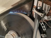
I used a 1cm^2 aluminum foil, and it detects at a great distance. The CNY17 is a low end part, I know. I don't have much daylight by by TT so no problem.
I designed a 0.6mm PCB that would fit under my sub-platter, with 30 precision spots for a higher feedback frequency. The problem with a single spot is that it may fall in a peak or valley of a low frequency wow. Possibly a divide-by-N chip could be used for data reduction, to 1 pulse per rev. but software would be better.
The picture was taken with my LG phone and looks much worse than the real thing. The camera has problems with the light contrast of the LED and OLED, and I cannot get a good pic :-(
Last edited:
This application guide discusses various materials that can trigger the sensor, in case it’s of interest to others:
https://www.vishay.com/docs/80107/80107.pdf
My circuit is similar to Figure 18.
https://www.vishay.com/docs/80107/80107.pdf
My circuit is similar to Figure 18.
Last edited:
Unfortunately I am still having issues with overhead recessed incandescent bulbs.
Would increasing the current through the diode help - maybe there just isn’t enough IR light. I am using the white sticker dot. The datasheet says the osram part has a daylight filter, but perhaps I need something different to combat the bulb?
Would increasing the current through the diode help - maybe there just isn’t enough IR light. I am using the white sticker dot. The datasheet says the osram part has a daylight filter, but perhaps I need something different to combat the bulb?
Attachments
...sorry I meant I use the CNY70, not the -17.
One photo sensor the 1KOhm series resistance was not enough from 5V, so a lowered it to 500Ohm, which worked.
1KOhm would give you approx 3.9mA for an IR diode that is rated for up to 50mA, so maybe a bit optimistic.
One photo sensor the 1KOhm series resistance was not enough from 5V, so a lowered it to 500Ohm, which worked.
1KOhm would give you approx 3.9mA for an IR diode that is rated for up to 50mA, so maybe a bit optimistic.
...sorry I meant I use the CNY70, not the -17.
One photo sensor the 1KOhm series resistance was not enough from 5V, so a lowered it to 500Ohm, which worked.
1KOhm would give you approx 3.9mA for an IR diode that is rated for up to 50mA, so maybe a bit optimistic.
So you ended up with around 7.5mA (5-1.25)/500? Yeah, I am at only 1mA - maybe that’s my issue.
- Home
- Source & Line
- Analogue Source
- Digital Tachometer for record player (LCD display)