I now have basic proportional only error correction code running on the Arduino tach, it now sends up/down button presses to the SG4 motor controller to manage the speed. It looks like I will be limited by the fact that a single SG4 button press is 0.01 Hz / 1.5 Hz/rpm (with 50 Hz motor) = 0.0067 RPM per button press. So it makes sense I am getting up to +/- 0.01 RPM hunting. I will add in an error integration function as suggested to hopefully reduce the toggling.
I just ran a test album with the P code enabled. It initially took about 30 seconds for the speed to stabilize at 33.33 RPM. When I drop the needle, it slowed to 33.18 Hz (stylus drag) and took about 20 seconds to stabilize. While playing the first side, it now makes 0.01 frequency corrections anywhere between 5 and 40 seconds and the RPM display varies by +/- 0.01 RPM. When playing the 2nd side, it is minutes between frequency corrections, I assume as the motor is warm and stabilized. This is much better than the 0.2 - 0.4 RPM variance I would see without feedback control.
Right now the code only simulates one button press per loop, hence the longer time needed for initial stabilization:
if (abs(INSTERROR) > MINERROR && INSTERROR < 0) { //* Speed is slow, bump up by one button press
digitalWrite(UP,LOW); //* set low as an input
pinMode(UP,OUTPUT); //* now we're sourcing current as an output, i.e. GND
pinMode(UP,INPUT); //* now we're tri-stated back as an input
}
else if (INSTERROR > MINERROR && INSTERROR > 0) { //* Speed is fast, bump down by one button press
digitalWrite(DOWN,LOW); //* set low as an input
pinMode(DOWN,OUTPUT); //* now we're sourcing current as an output, i.e. GND
pinMode(DOWN,INPUT); //* now we're tri-stated back as an input
Any suggestions as to how to simulate multiple button presses to converge more rapidly?
Just repeat your button press routine, but put at least 50mS between them (the SG4 delays 50mS for debounce time).
You should be able to leave the pin defined as an output and just toggle between HIGH/LOW/HIGH for a button press. You may want to add a short delay when the pin first goes low; if it goes back high too fast, the SG4 may miss it.
You should be able to leave the pin defined as an output and just toggle between HIGH/LOW/HIGH for a button press. You may want to add a short delay when the pin first goes low; if it goes back high too fast, the SG4 may miss it.
If you are calling delay(500) in your init routine, it doesn't look like it is disabled.
If it is, my original sketch had mydelay() routine that you can call that does not use a timer interrupt.
If it is, my original sketch had mydelay() routine that you can call that does not use a timer interrupt.
Thanks, I'll mess with mydelay. I am trying to set up a loop that halves the error with multiple pulses each time to converge more quickly. At this point I only get a single pulse. Once I am close it behaves well.
I'm an Arduino noob, so it is taking a while ...
I'm an Arduino noob, so it is taking a while ...
They completely depend on the entire system. That is your code performance , output stages, SG4, amplifier, transformer, turntable and feedback sensor. Realistically they have to be determined on site by tuning aka experimentation. ;-)
Thanks Steve, but I am too far down this path to toss it.
Any pointers on starting values for Kp, Ki, Kd?
So I reworked the code and added a PID algorithm. I am able to get multiple button pushes in a row with debounce delay as suggested by Bill. Speed now stabilizes in less than 10 seconds when I drop the needle or change speed. I am only auto correcting speed when within 1%, as I have found that if there are two many "button pushes" in a loop, the RPM is affected. This also makes sure that the algorithm is not fighting speed when switching between 33/45 as it only kicks in when the speed is settling down.
I made the assumption that time through the loop is constant in order to simplify the PID calculation. This is clearly not correct, but since the time functions are disabled, I didn't have much of a choice. Anyway, it seems to work reasonably well if I don't do large corrections. Since the SG4 remembers the last frequency for each speed, it will be reasonably close to start with (within 1%) and the algorithm works ok.
I have found with the Lenco motor that speed increases with the stylus off the record by around 0.11 RPM, and as the motor warms up the frequency needs to increase by about 0.3 Hz to maintain proper speed. With this additional code providing a feedback loop to the SG4, I can automatically compensate for both these effects and maintain constant speed to 0.01 RPM. Not bad considering the limitations!
I have attached my code, any suggestions as to how to do this more elegantly are appreciated.
Attachments
Stupid question and maybe it was already answered in previous threads, but anyway and can you please also upload diagram of close-loop wiring from tacho to SG4? I want to try it.
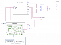
See attached. I use 4 Arduino digital I/Os, wired to the SG4 as shown in the diagram:
PIDACTIVE (Input, 5): I added a switch to be able to turn the auto correct software routine on/off
SPEED (Input, 6): Reads the status of the 33/45 switch to determine the desired SETPOINT RPM (33.3/45)
UP (Output, 7), DOWN (Output, 8): Arduino outputs that apply the speed correction pulses to the UP/DOWN switches on the SG4 board to correct to the SETPOINT.
Note that the pads to connect to are on the outermost edge of the board.
You can still use the SG4 switches to manually adjust the frequency, either when the autocorrect is running or switched off.
Attachments
From a debugging standpoint, it is easiest to make SETPOINT=33.33333 and comment out the SPEED and PIDACTIVE code initially. Get the basic button pushes to work from the Arduino, fiddle with the PID constants to get a reasonable settling time. Then you can add the capability back in to switch speeds and turn the code on/off .
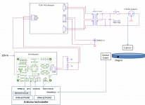
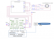
I revised the diagram, adding the tach sensor for completeness
I updated your diagram for phase-shift split motor run setup.
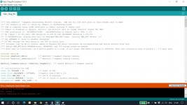
Also, have an error on your sketch during "Verify" (please see attached). What Arduino board is used there? I have Uno.
I believe I must update you PID sketch for my type of display. Can you please help me to mod it? I can send you my sketch.
Attachments
I think your sketch is updated correctly with my OLED display setting now, however I need to find some way to avoid lock due to interference with optical encoder circuit. Any advice is welcome. I can install some“OR” type of toggle switch, but it might be some more elegant solution already exist...
I added toggle switch to turn off encoder and enable PID. All is working fine now. Very promising and my compliments to you, robnik33!!! Excellent work!!!
Question that I have is how to optimize parameters?
I use your initial setup now (int kp = 1, ki = 0.4, kd = 0.2) and all is fine when I start to go down from high speed. It is stays tight for couple min and when speed is bit down, it is remains 33.316-33.3120 without adjustment. Adjustment starts when speed is at 33. 311, but not overshoots 33.320.
So, what to change?
Thank you a lot for that feature.
I am no expert here. There are many references for PID tuning. I didn't find them particularly useful. I used trial and error, mainly adjusting Ki and Kd to get a reasonable settling time when you drop the needle without oscillating around the setpoint. I ended up about 10 seconds, but it stays stable long-term. If you want greater changes initially, change Kp. You may also want to try 2% as the limit where the algorithm operates.
Also, if you are not settling at the exact speed, I used a 1/2 pulse offset to try and avoid the last digit toggling. You are limited by the minimum 0.01 Hz steps, that's why I went with 2 significant digits in the display.
I understand all limitations and I agree that without marathons for empirically found parameters will be impossible to reach desired result for every individual setup. BTW, it is already way better speed stability now vs. how it was with open loop. So, I’ll start with 2% first. Kp=10 will be later on for test.
Is it right for code change?:
if (RPM > SETPOINT * 1.99 && RPM < SETPOINT * 2.01) { //* only autocorrect if speed is within 2%
Is it right for code change?:
if (RPM > SETPOINT * 1.99 && RPM < SETPOINT * 2.01) { //* only autocorrect if speed is within 2%
robnik33 hit on a key point: The minimum step for speed change is 0.01Hz which will limit the resolution of the target speed. This project was never intended for automatic adjustment; if it was, I would have used a different scheme to increase the resolution (the Eagle/Falcon & now SOTA Condor has a frequency resolution that is 18x finer or 1/1800 Hz). The frequency resolution of the SG4 was kept the same as the VPI SDS so that manual adjustment would not take forever to arrive at a target speed.
That being said, it was quite an accomplishment to get the auto correct to work as well as it does on your system. Good work robnik33!
That being said, it was quite an accomplishment to get the auto correct to work as well as it does on your system. Good work robnik33!
Alexkosha,
For +/- 2% the statement is
if (RPM > SETPOINT * 0.98 && RPM < SETPOINT * 1.02) { //* only autocorrect if speed within 2%)
The 1 or 2% just sets the range where the algorithm works. It is part of the tuning when you are trying to reduce the time to converge. Basically 2% starts the algorithm when the speed is a little farther out from target, and may result in larger initial corrections, which then impacts how quickly the PID algorithm settles down. So I suggest staying with 1% initially and play with the PID parameters as you drop the needle and time the delay to converge on the setpoint. Larger Kp will make more aggressive changes and if you are overshooting the target, it is probably too large. 10 is probably too much, but hey it is software, easy to try!
- Home
- Source & Line
- Analogue Source
- Digital Tachometer for record player (LCD display)