I agree. It is very beautiful tachometer. You are very talented person.
It will be nice to allow (if it is possible and in addition to IN12/IN12B tubes) to connect any tube type that someone like the most with plat cable on separate PCB. In other words, is it practical to separate tube section PCB from mail circuit PCB? If not, then we can run wires from such PCB to tubes as point to point. 🙂
It will be nice to allow (if it is possible and in addition to IN12/IN12B tubes) to connect any tube type that someone like the most with plat cable on separate PCB. In other words, is it practical to separate tube section PCB from mail circuit PCB? If not, then we can run wires from such PCB to tubes as point to point. 🙂
The two PCBs are identical except for the tube connections. The boards were laid out in Eagleware and are easy to modify for different types. I'll start a separate thread on this as soon as I clean up the documentation a bit.
Hi pyramid,
Very retro, and much to my liking. I too would be interested. Once again thanks for your expertise and having interesting projects for us DIYers.
Kevin
Very retro, and much to my liking. I too would be interested. Once again thanks for your expertise and having interesting projects for us DIYers.
Kevin
Hey Bill
As usual 1st class job. Your help in the diy community is priceless!!! Will be looking forward to your new thread.
Thanks
Tom
As usual 1st class job. Your help in the diy community is priceless!!! Will be looking forward to your new thread.
Thanks
Tom
One more question... Is it any possibility to add some relatively frequent “slot machine effect” run to the source code for all tubes and all cathodes? That can help to prevent “cathode poisoning” and extend nixies lifetime.
One more question... Is it any possibility to add some relatively frequent “slot machine effect” run to the source code for all tubes and all cathodes? That can help to prevent “cathode poisoning” and extend nixies lifetime.
Cathode Poisoning on Nixie Tubes
One more question... Is it any possibility to add some relatively frequent “slot machine effect” run to the source code for all tubes and all cathodes? That can help to prevent “cathode poisoning” and extend nixies lifetime.
Had not heard of that before. The firmware currently has a lamp test mode where it will illuminate each digit 0-9 for 3 seconds each of tube #1, then do the same for tube #2, etc. In normal operation, the display is multiplexed, but troubleshooting a mux display is difficult if something is not working correctly. The lamp test mode operates in static mode (only one digit/tube at a time) and removing the test jumper will freeze the display in that digit/position for easy trouble shooting. Reinstalling the jumper will resume counting. Right now, the test ends after displaying "9" on tube #5, but I can have it loop around to the beginning and run endlessly.
Because the display is muxed, the current limiting resistor is smaller than normal as each tube is only on 1/5 of the time. In test mode, the current will be higher 100% of the time, so will act as a rejuvenater for the cathodes.
Hi Pyramid
Just wondering if you can put a ballpark figure on the nixie display project that would cover starting a build from scratch? PCB, tubes/components, preprogrammed IC etc?
I’ve had my SG4 project with your chip amp and the Anaheim motor up and running for a while now with the Roadrunner integrated but not being able to use the feedback loop that was designed for the Falcon.
I figured I have at least one more turntable project left in me, so I’m in on scobham’s Arduino based controller group buy so I can have something with feedback speed control.
Since I’d be building something mainly from scratch next time I’d take the time to build a nixie display to integrate.
BTW...if you ever decide to figure out a feedback solution for a tachometer with the the SG4 I would be first in line.
Attachments
Still working on the documentation, but a BALLPARK figure would be:
PCB: $32.50 ea ($97.60 for a set of 3).
Digikey Parts: ~$36
HV supply: $15
I bought the tubes and HV supply at [url]www.shop-tes.com[/URL]. 5 x IN12 =$31 (4 type A, 1 type B w/decimal point). 5 x IN16=$45
For the IN12 version add $23 for socket pins for the tubes which I highly recommend. The IN16 tubes have to be soldered to the PCB and are a real bear to do.
Is there a link for buying these?
Or if someone is building this please message and let me know the cost to build and ship it
Or if someone is building this please message and let me know the cost to build and ship it
Hi Pyramid,
As the British would say - "All in your good time old chap" - and I mean it. The projects you have made available here are damn well thought out, and your documentation is thorough. That is not easy, and as a relative newby, I can appreciate the time and effort you put into it - for nothing - except probably for the enjoyment thereof. I can wait.
Regards, Kevin
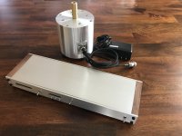
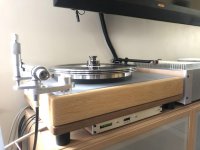
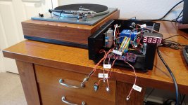
I previously built a Pyramid SG4 motor controller for my 50Hz Lenco L75 that I am running at 60 Hz here in the US. Works great and kudos to Bill for an excellent design. I wanted to add a tachometer in the same enclosure, but using a 7-segment LED display. I now have it working!
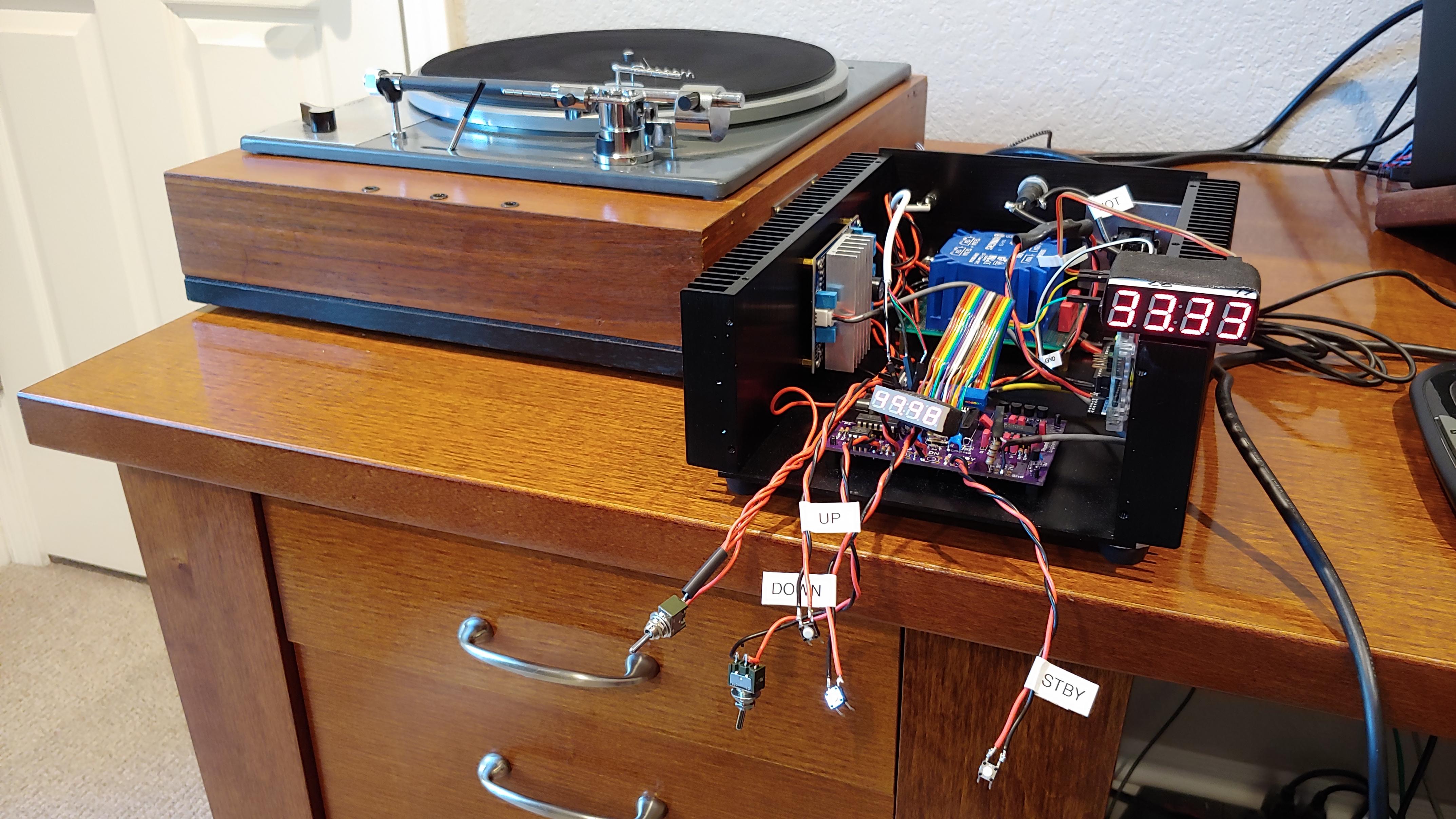

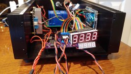
The enclosure is overkill with the heatsinks, but it was the right size. Everything runs super cool and barely warm to the touch. I am waiting on the final switches to complete the faceplate. I like having the large display for RPM and the smaller SG4 display for frequency. Now I can monitor and fine tune the RPM on the fly, sweet!
The display is an Adafruit 0.56" I2C LEDBackpack, available in many colors and also (sometimes) available on Digikey.
0.56" 7-Segment Backpack | Adafruit LED Backpacks | Adafruit Learning System
I haven't programmed since college many eons ago, but was able to get it working relatively easily. The display will show --.-- when the platter is not running, and displays RPM to 2 decimal places, ie 33.33 or 45.00 when running. I was not able to get the cursor to blink to signify the sensor working, the best I can tell you can only blink the entire display, not just a single element. Maybe someone with more programming skills can figure it out if desired.
I attached the edits I made to what I think is Bill's latest code, commenting out the existing display code. Please don't laugh at my rudimentary programming skills!
Attachments
Bill,
Now that I have been running my Lenco for awhile, I do notice a slow speed drift as the motor warms up. Generally less than 0.2 RPM over about 20 minutes. For now I manually use the up/down switches to correct. Got me to thinking of using the Arduino to send up/down pulses to the SG4 switches to correct the drift. Any thoughts or recommendations?
Now that I have been running my Lenco for awhile, I do notice a slow speed drift as the motor warms up. Generally less than 0.2 RPM over about 20 minutes. For now I manually use the up/down switches to correct. Got me to thinking of using the Arduino to send up/down pulses to the SG4 switches to correct the drift. Any thoughts or recommendations?
I looked at your modified code and everything looks OK from what I can tell (not familiar with the LED shield). One thing that did stick out: You call delay(500) at the end of the setup; this should hang the UNO as timer 0 is disabled (there is a warning about this in the header). Unless you UNO is using a different timer for this function, in which case it should be disabled to prevent random timing errors.
As far as feedback, the resolution of the SG4 may not be fine enough; you could try it, but you may find it will "hunt" up/down in speed. You can minimize hunting by setting a "window" where errors smaller than a preset level will be ignored, but if they exceed the threshold, than a proportion of the error is feedback to the SG4 as correction. You can also average (integrate) the errors and add a proportion of that term to the correction term. This is the basis of a PI (proportional/integral) controller. Adjusting the P and I correction amounts will give you a target response, but settling time and correction time are opposing results.
As far as feedback, the resolution of the SG4 may not be fine enough; you could try it, but you may find it will "hunt" up/down in speed. You can minimize hunting by setting a "window" where errors smaller than a preset level will be ignored, but if they exceed the threshold, than a proportion of the error is feedback to the SG4 as correction. You can also average (integrate) the errors and add a proportion of that term to the correction term. This is the basis of a PI (proportional/integral) controller. Adjusting the P and I correction amounts will give you a target response, but settling time and correction time are opposing results.
Thanks Bill, I am going to play around with the Arduino PID library to see what I can come up with.
Hi, you might be interested in this project. The work around PID has already been incorporated. A pre programmed arduino is available. We see <0.005% wow on L75's.
http://https://www.diyaudio.com/forums/group-buys/349742-turntable-tachometer-motor-speed-controller.html#post6086530
http://https://www.diyaudio.com/forums/group-buys/349742-turntable-tachometer-motor-speed-controller.html#post6086530
Hi, you might be interested in this project. The work around PID has already been incorporated. A pre programmed arduino is available. We see <0.005% wow on L75's.
http://https://www.diyaudio.com/forums/group-buys/349742-turntable-tachometer-motor-speed-controller.html#post6086530
That link didn´t work Steve..
I think this will:
https://www.diyaudio.com/forums/gro...er-motor-speed-controller-21.html#post6268634
- Home
- Source & Line
- Analogue Source
- Digital Tachometer for record player (LCD display)