"It's not until at or above the dipole peak that you start to see the effects of baffle diffraction appear, and only if/when the baffle width is at least about 1.5 to 2 times the width of the radiating surface of the driver."
Right, that's what I thought, and why I didn't understand when you said:
"Firstly, diffraction is not what gives rise to oscillations in the on or off axis response from a dipole"
Right, that's what I thought, and why I didn't understand when you said:
"Firstly, diffraction is not what gives rise to oscillations in the on or off axis response from a dipole"
I didn't understand when you said:
"Firstly, diffraction is not what gives rise to oscillations in the on or off axis response from a dipole"
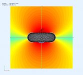
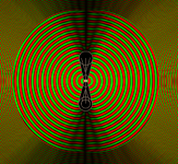
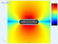
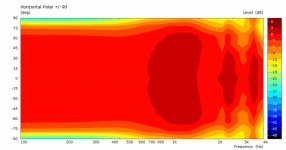
The "oscillations" in the image below are not caused by diffraction, since there is none. That is what I am talking about in the quote above. I probably should have used the term "response shape" but you were using the term "oscillations" in this post, so I picked up on that. Perhaps we are thinking about different things when we refer to "oscillations"?

Let me post and answer some questions to lead you through how I think about diffraction in dipoles (and other systems too).
Hi Charlie, thanks for that lengthy explanation and the insight.
The other end of the spectrum is the point source (or small source) in a relatively large baffle compared to the source size. This will have a strong diffraction occurring at the edge. This is the situation when there is a small driver (sometimes a fullranger) in a large baffle - expect diffraction problems.
This is what Olson did to get his diffraction graphs. He used a 7/8inch custom driver on up to 24inch baffles to make his point clearer. Fair enough. In reality the ratios are lower and the diffraction peaks are lower, so a circle (or other shapes) might be acceptable based on dimensions.
What about the torus baffle shape?
I view the torus as an interesting combination that might actually work to reduce the amount of observed diffraction for small drivers in relatively large baffles. The curved edge of the torus will smear out the diffraction signature AND will provide a long pathlength between front and rear that can help to reduce the dipole losses.
At the same time, I do not expect the torus to do anything to the dipole pattern itself. A low frequencies the front and rear waves can still propagate everywhere and combine to forum the dipole response. At higher frequencies they waves can still "wrap" around the edges of the torus. It's only in a critical frequency band where the smearing of the wavefronts along the curved edge might lead to some interest changes. Note sure. One way to prevent front and rear wave interaction is to shape the "torus" into a horn or strong waveguide that has high directivity. At that point it will likely not strictly be a true torus and I am not sure what others have in mind for the "shape" exactly.
I do have some experimental data that suggests that MIGHT be possible. I have constructed a dipole from two 1" dome tweeters in small (circa 4") waveguides. From what I can tell, and guess, around 1kHz the separation distance just happens to be enough for constructive interference, and the SPL is raised there. If the real system followed the two-monopole model, as frequency increases there would be a series of peaks and nulls. Instead there are none at all. I believe that in this frequency region the waveguide becomes effective and the front and rear waves no longer wrap around to the opposite side. You get a very nice, near constant directivity pattern from the pair! Maybe these effects can be scaled up in size for larger drivers?
Hopefully you'll hang around for this and offer suggestions/critique. I suspect there will be several models presented.
.
Gotcha. Yes, I was talking about the on axis nulls above the dipole peak. BTW if you want to see the smearing effect of the torus baffle have a play with the ripple tank simulation, you can make a "waveguide" too, visually it can give a good idea of what's happening.
For completeness we should probably see the same driver modelled for the Torus shape?
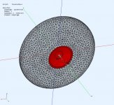
Of course. I have it, but I don't like it. I was just waiting for feedback on the disc.
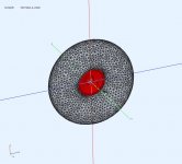
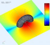
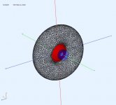
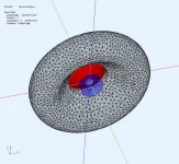
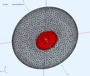
Here is the torus, ID=150mm, OD=450mm, rotated circle OD=150mm. Same driver as the torroid (disc).
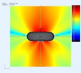
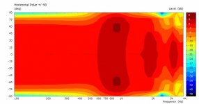
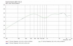
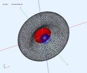
A few thing that stand out. The driver is mounted midway in the torus. The recess is causing HF issues with the woofer front and partial obstruction of the back. The front could be fixed by a flush mount or different exit contour. There is less clearance around the magnet and its causing field asymmetry. The lateral null has widened, but I'm not sure if this is good or not. However It did seem to reduce the axial ripple (nulls?).
A few thing that stand out. The driver is mounted midway in the torus. The recess is causing HF issues with the woofer front and partial obstruction of the back. The front could be fixed by a flush mount or different exit contour. There is less clearance around the magnet and its causing field asymmetry. The lateral null has widened, but I'm not sure if this is good or not. However It did seem to reduce the axial ripple (nulls?).
Attachments
-
 TorusFrontView.jpg63.8 KB · Views: 254
 -
 ObsField@2K7Hz.jpg44.3 KB · Views: 110
 -
 ObsField@1K5Hz.jpg44.9 KB · Views: 105
 -
 ObsField@500Hz.jpg43.6 KB · Views: 110
 -
 ObsField@300Hz.jpg37.2 KB · Views: 124
 -
 TorusField@300Hz.jpg51 KB · Views: 124
 -
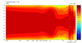 TorusPolar@3m.jpg25.5 KB · Views: 252
 -
 Torus_FR@3m.jpg34.5 KB · Views: 255
 -
 TorusRearView.jpg61.3 KB · Views: 252
Last edited:
Yes, the null will widen and not be as deep. I've found a simple straight waveguide helps the consistency of the null. This is ridiculously large but you get the idea, I attach the file as well if you want to change anything
Attachments
It's not a problem to make the baffle lossy. The issue is getting a model of something real. I use a simple first order model that starts to absorb at some frequency. I do this to model my carpet for floor bounce effects.
Next torus model is already made. 🙂
I tend to think a wider null is better for reduced lateral reflections, but there will a cost with reduced forward beam width. So I'm not sure of how that nets out.
Next torus model is already made. 🙂
I tend to think a wider null is better for reduced lateral reflections, but there will a cost with reduced forward beam width. So I'm not sure of how that nets out.
This is a torroid OD=450mm, ID=150mm, T=110mm, RoundOver=50mm and a generous chamfer (70mm) on the back to let the woofer breath.
.
.
Attachments
-
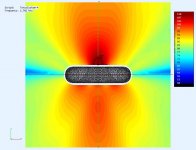 ObsField@2K7Hz.jpg46.7 KB · Views: 125
 -
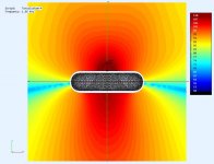 ObsField@1K5Hz.jpg47.9 KB · Views: 114
 -
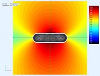 ObsField@500Hz.jpg46.6 KB · Views: 117
 -
 ObsField@300Hz.jpg46.4 KB · Views: 132
 -
 CustomV4-ObsField@300Hz.jpg50 KB · Views: 258
 -
 CustomV4-Polar.jpg25.5 KB · Views: 255
 -
 CustomV4-FR@3m.jpg34.3 KB · Views: 254
 -
 CustomV4Rear.jpg114.5 KB · Views: 253
 -
 CustomV4Front.jpg119.6 KB · Views: 253
Is that what SL is referring to here? Frequently Asked QuestionsEarl Geddes, from what I recall, is opposted to open baffle speakers because he feels they have "twice the diffraction" of a regular speaker: diffraction off of the baffle edge once from the front radiation, and diffraction off of the baffle edge once from the rear radiation. I find that argument rather academic and specious.
"If I have not lost you by now, then let's talk about open baffle diffraction effects with the above in mind. Assume a small unenclosed piston source in the center of a circular, flat baffle. The source radiates towards the front and with opposite polarity towards the back. A pressure increase in front is associated with a pressure decrease in back of the baffle. Observing again the response to a stepwise increase in pressure at some on-axis distance in front of the baffle, we see the initial pressure increase, which drops to 1/2 when the edge diffracted front side wave arrives. At the same time we also receive from the backside of the baffle that 1/2 portion of the wave, which was diffracted around the baffle edge into the frontal hemisphere. The 1/2 of the backside wave is of opposite polarity to the front wave and together with the front edge diffraction cancels the front wave completely(!). If the baffle had a 12" (0.3 m) diameter, then we would observe a 0.15m / 343m/s = 437 us duration pulse in response to the pressure step from the point source."
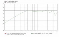
Nasty ? it's 5dBpp just like all the previous ones, only spread out more a bit more.
I wanted the woofer to be flush but I ended up moving it back 0.5cm to help flatten the FR. If I were in marketing that curve would be +/-2.5dB 🙂. The HF is preserved by moving the woofer to the front so the curve is flatter.
Next model will change the baffle diameter to help that "nasty dip" . 😀
I wanted the woofer to be flush but I ended up moving it back 0.5cm to help flatten the FR. If I were in marketing that curve would be +/-2.5dB 🙂. The HF is preserved by moving the woofer to the front so the curve is flatter.
Next model will change the baffle diameter to help that "nasty dip" . 😀
Hehe, it's not much better than the simple disc, that's what I mean "nasty" 😉 I experimented with driver near the front, it didn't work well. Try a minimal waveguide see what happens
Everything is an option at this point 😀 but I like to explore a direction before changing course.
I'm glad you are finding it interesting. So far it's paralleling what I found with the ripple tank but is a far better tool for the job.
Similar to post #90, with the woofer recessed 30mm and woofer exit round over. The woofer exit still needs work as its causing ripple @ >2Khz.
.
.
Attachments
The ripple tank simulation uses an "ideal" dipole source, so symmetry was easy. When I introduced any asymmetry it effected the way the diffractions were smeared at the "edge". Since this is a different approach to spreading the diffractions as a rectangular baffle would do, symmetry, I think, is more important. This is why I was also thinking of back-to-back drivers.
Similar to post #90, with the woofer recessed 30mm and woofer exit round over. The woofer exit still needs work as its causing ripple @ >2Khz.
.
I know you are interested in investigating this "torus" shape, but that might not be a useful profile above e.g. 2kHz no matter what you do.
Can you simulate other cross-sections that are rotated around the central axis to create the solid shape? I would be interested to compare the torus results to more waveguide or horn profiles. Where the inner surface end (e.g. the termination of the horn lens) you would just join to the other termination (e.g. front to rear) using some kind of gentle roundover.
Like two of these, back to back and joined together at the edges of the guide:
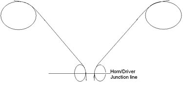
You will probably end up with something that is more like a cylinder with bulging sides and a horn in each end.
- Home
- Loudspeakers
- Full Range
- Did Siegfried Linkwitz miss a trick?