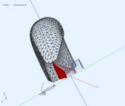
The relative driver position in the torus helps cancel the dips so I'm reluctant to move it just yet. I'm open to other profiles as discussed but I need another "kick at the can" on the torus. I went though 6 iterations to get the thickness (110mm) and driver position (25mm recess) for that diameter torus (450mm) and driver (150mm less 10mm suspension).
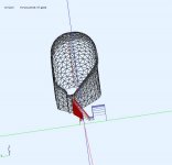
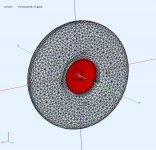
I think the driver front needs clearance and an exit cone/profile that flares fast enough to not interfere with the beam as it narrows. This is a cross section of the last torus.
I think the driver front needs clearance and an exit cone/profile that flares fast enough to not interfere with the beam as it narrows. This is a cross section of the last torus.
Attachments
Last edited:
I see, you want an equal distance around the profile to the "edge", it is a balancing act. 🙂 How about keeping that pear shaped profile similar but twisting it around as you move the driver back, if you see what I mean. Like my pinched wheelbarrow tyre 😉 PS, I'd still call it a torus(pear)
Last edited:
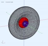
If you are looking for fixes to the rearward radiation, you could add a bullet shaped phase plug to the back of the magnet having a diameter equal to that of the magnet.
I remember the guys at Rethm had great success mounting a 'cone' on the back of the magnet and closing in the gaps around the frame - not sure if they still do this - I think Dave (Planet 10) still does some of this too.
I've been looking at the petal baffle designs of Mattes and these have a lot of the attributes we're looking at here (see Torus thread)
I've been looking at the petal baffle designs of Mattes and these have a lot of the attributes we're looking at here (see Torus thread)
@Charlie - I tried making the magnet artificially small to see the effect on the front field @3m and it was a small effect (1dB) on the ripple.
@jameshiij - The idea I like to vary the perimeter like a petal baffle. I don't think I'm at the point where just diffraction is remaining, there are other issues.
@jameshiij - The idea I like to vary the perimeter like a petal baffle. I don't think I'm at the point where just diffraction is remaining, there are other issues.
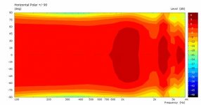
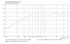
Another trial to fix the woofer exit and this looks better. The woofer has clearance and a conical exit. There is still ripple but the average response is more flattish now.
I also did a few test runs changing the magnet size, and removing radius on rear edges and the forward ripple was still there.
.
I also did a few test runs changing the magnet size, and removing radius on rear edges and the forward ripple was still there.
.
Attachments
-
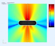 Torus4f-ObsField@4Khz.jpg31.6 KB · Views: 143
 -
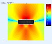 Torus4f-ObsField@2K5hz.jpg30.5 KB · Views: 131
 -
 Torus4f-ObsField@2K1hz.jpg30.4 KB · Views: 117
 -
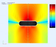
 Torus4f-ObsField@1Khz.jpg30 KB · Views: 134
 -
 TorusV4f-polar@3m.jpg25.9 KB · Views: 168
 -
 TorusV4f-SPL@3m.jpg34.2 KB · Views: 431
 -
 TorusV4f-section.jpg46.4 KB · Views: 411
 -
 TorusV4f-Rear.jpg100.2 KB · Views: 404
 -
 TorusV4f-Front.jpg100.2 KB · Views: 404
The smearing of the diffractions around the "edge" of the torus appear to work well at low to mid frequencies, a simple, shallow conical waveguide may be able to push the useful range higher, or may not be necessary at all due to driver beaming.
Hmm, wish I had my notes! I remember basing it on some Altec woofer measurements of their 'deep' curvilinear 15" Vs the 'shallow' JBL variant, which were really smooth out to ~[Fs*8pi], so used this to form the front, back and whatever semi-circle closed it at that point, but can't remember anything about the 'FR' driver, so no clue about dimensions plus it was rectangular, so wouldn't be as good as a half doughnut, but John couldn't believe how well it performed.
GM
Another trial to fix the woofer exit and this looks better. The woofer has clearance and a conical exit.
Thanks for the work so far!
 Curious if my assumptions based on a curvilinear woofer with a driver for a dust cap has/had any real merit for the effort it took to build.
GM
When you look at the response, it's something like +/- 2.5dB at 3 metres and the forward distribution looks to be remarkably good across that same range - the rear distribution isn't so critical if it doesn't effect the front radiating pattern.
I'd be very pleased indeed to get an actual performance like this at home as the vagaries of the room would be more significant on the response performance.
Thanks Don for all shape/response trials - it certainly gives an immediate indication and a great followup on the Scott/Alan/etc modelling
I'm fascinated by the amount of detail and efforts Mattes has put into his petal design.
That's looking good Don 🙂 Did you try what I suggested in post 122 or did it screw up the HF again?
Interference patterns to the rear reduce the energy at the edge, the more equal that is the better the cancellation. As you say, it probably doesn't matter to much, at the frequencies involved there will be other issues anyway.the rear distribution isn't so critical if it doesn't effect the front radiating pattern.
Oh yeah, forgot about that - perhaps if the outer circumference or edge was absorbent at the higher frequencies, this might also reduce the edge diffractions too - no idea if this could be modelled.
I wonder, Don, if it would be possible to alter the outer shape without changing the inner surfaces - perhaps like stretching the top/bottom outer curves to produce altered perimeters this way as a different way to get that petal effect - again, not sure if it could possibly be modelled/muddled either.
I wonder, Don, if it would be possible to alter the outer shape without changing the inner surfaces - perhaps like stretching the top/bottom outer curves to produce altered perimeters this way as a different way to get that petal effect - again, not sure if it could possibly be modelled/muddled either.
Don said the baffle could be made lossy in the model, that may be useful, I'm not sure, it could help with high frequency diffraction and low frequencies would largely still see it.
I was thinking a flexible mockup could be made with something like an inner tube or tyre, and a number of inserts cut to the shape of the cross section together with rings holding the torus in different shapes.
I was thinking a flexible mockup could be made with something like an inner tube or tyre, and a number of inserts cut to the shape of the cross section together with rings holding the torus in different shapes.
I've got a 'pliable' hot knife ordered (to cut curves in the foam) but Covid has slowed things down but the basic straight one could carve a reasonable 'rounded' shape I guess - the inside radii will be tiresome but 'do-able' I think - so that's a possible starting point.
And to think that I only recently dumped the old electric potter's wheel in the annual hard rubbish collection and could have 'thrown' a solid version!
I've got mostly 8" or 10" FR drivers so the torus will be 'bit big'.
I remember some years ago about a European OB design that had a horizontal curved front and used some vanes or fins at the back and I tried this idea on a Maggie at that time with some improvement in widening the listening area of the Maggie quite a lot - anyone recollect anything like this?
Great work DonVK! I wonder how a simple flower petal (5 petals) made from flat plywood would compare to a torus?
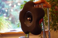
These are flower petal baffles made by member mattes from EVA foam with more 3D sculpting. But I wonder if a flat flower baffle might work as well. Perhaps still a round over on the edge.
These are flower petal baffles made by member mattes from EVA foam with more 3D sculpting. But I wonder if a flat flower baffle might work as well. Perhaps still a round over on the edge.
Attachments


Last edited:
It would be a riot of spread out edge diffractions 🙂 I'll bet Mattes' is so good because of the large round overs.
Actually you said it first, I was just using your terminology 🙂The "oscillations" in the image below are not caused by diffraction, since there is none. That is what I am talking about in the quote above. I probably should have used the term "response shape" but you were using the term "oscillations" in this post, so I picked up on that. Perhaps we are thinking about different things when we refer to "oscillations"?
The reason I bring this up now is that there still appears to be some confusion about what is happening.In a dipole speaker it is front-to-back pathlength differences that give rise to cancellation or addition of the front and rear waves, and these result in the oscillations. Using a toroidal baffle shape will not change that.
The reason I bring this up now is that there still appears to be some confusion about what is happening.
At low frequencies the object (baffle) is too small to diffract. THere is no diffraction. Waves propagate as if the baffle does not exist, and the source acts like a monopole.
At high frequencies the source itself will be directional (talking about a woofer here, not a small tweeter). So the source does not really illuminate the baffle - acoustic energy is directional (this ignores, the basket and magnet, etc. that's a separate issue on the rear side). So, again, no diffraction is occurring because the edge of the baffle is not getting illuminated at HF.
Somewhere in between the wavelengths will get small enough to be comparable (or smaller than) the baffle dimensions. At these frequencies the wave "sees" the baffle as an obstruction. When the wave reaches an edge it WILL diffract. But the degree to which this happens and appears in a measurement is IMHO dependent on the relative size of the source and baffle:
- source size = baffle size : this is the nude driver case. Because the source is distributed in space, diffraction is distributed (smeared out) in both space and time and is not observed
- source size < baffle size < 2 times source size : even though there is a finite baffle the size of the source still causes spatial and temporal smearing of edge diffraction, so diffraction is still not significant
- baffle size > 2 times source size : The temporal smearing gets reduced to the point at which you see changes to the response from the diffraction signature. The changes can be quite different as a function of angle
I use the word "size" above to mean length or diameter.
In this thread my earlier post #80 talked about this in terms of a two-monopole model, and "real world" drivers and baffles. I wrote:
I probably should have been more clear when I wrote the above that I was thinking of the "two monopole" dipole model, except for the last question for which I was thinking of real-world systems. So I probably just created some confusion there. I did mention that the two-monopole model of a dipole system is not valid starting and and above the dipole peak later on in that post:Q: How is the wave from one side of the baffle traveling around to the other side?
A: This depends on the ratio of the size of the radiating surface of the transducer and the size of the baffle. At low frequencies at least, the baffle is too small to change the propagation of the wave, and the source is small compared to the wavelength, so the wavefront propagates everwhere like a monopole in free space. At higher frequencies where edges can cause diffraction, the wave will still travel "around" the edge of the baffle to the other side but it no longer strictly a monopole because of the effect of the baffle and edge diffraction. At high frequencies the size of the radiating surface compared to the wavelength causes beaming and the baffle is not well illuminated, so wave propagation is no making it "around" the baffle to the other side (well not very much of it at least).
Q: What is causing the "oscillations" in the response of a dipole
A: These oscillations are caused by the interference, constructive and destructive, of the wavefronts generated from the front and back of the transducer when they meet out in the farfield. This depends on the path-lengths taken (which determines the relative phase angle when they meet). Wave that are in phase meet and add, and when out of phase cancel. If there are a variety of different pathlength taken, you have to add up all the different contributions from each. This is why the baffle shape and driver location on the baffle both influence the dipole pattern.
Q: What about diffraction in open baffle and dipole systems?
A: Without a doubt there is diffraction occurring, but that is not the primary reason behind the dipole pattern.
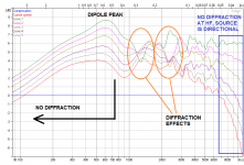
In the above quote I have highlighted my thoughts about diffraction and when it shows up for a dipole system. It's interesting that this cannot be said to happen at a certain absolute frequency per se, but only at a frequency that is related to (e.g. above) the frequency where the dipole peak appears. This is probably because of how the dipole system works, and the effect of source and baffle size as I have described above. It's a kind of interesting property of dipoles IMO.Moving from this model to a real system with a real driver on a finite baffle, we DO see this response shape up to a frequency which is about where the lowest "dipole peak" is found (e.g. 680Hz in the image above). This region encompasses both low and medium frequencies, the latter of which SHOULD show some diffraction even if it has only a modest effect. But real systems don't show these effects in this frequency range. It's not until at or above the dipole peak that you start to see the effects of baffle diffraction appear, and only if/when the baffle width is at least about 1.5 to 2 times the width of the radiating surface of the driver.
So, what does diffraction look like (it's signature) for a real-world dipole system? It's the ripples (OK, oscillations) in the response on axis and (probably) pinching or crossing of the on and off axis responses. I have attached a quick sim in the Edge with the area(s) highlighted - this is for a 40mm round cone in a 400Wx1000H (mm) baffle with the driver at x=0.2m, y=0.7m. Note that if I scaled up or down the sizes of baffle and source by the same factor, the pattern in the example would remain about the same but the frequency of the baffle peak and other regions will shift up or down proportionally.
Keep in mind that the Edge is a semi-realistic model with its own limitations. The driver is represented as a thin disc. There is no dished cone, no basket, no motor/magnet assembly, etc. These all have effects at mid and higher frequencies that are specific to their geometry. But I find the Edge easy to use and helpful for "what if" kind of decision making if you keep these limitations in mind. In the end, build a mockup, install the drivers, and measure the on and off axis responses to be sure what they are doing before building the final system and creating the crossover for it.
Attachments
Last edited:
[*]baffle size > 2 times source size : The temporal smearing gets reduced to the point at which you see changes to the response from the diffraction signature. The changes can be quite different as a function of angle
Diffraction, the way I understand it, is one phenomena, it will manifest in what appear to be different ways, that's all.
Regards the quote above, the torus is in this category. What is the angle you refer to, the polar angle, or the angle of the edge? It seems to me the curved "edge" of the torus increases the temporal smearing. How do you think the torus is having the effect it seems to?
- Home
- Loudspeakers
- Full Range
- Did Siegfried Linkwitz miss a trick?