Regards the quote above, the torus is in this category. What is the angle you refer to, the polar angle, or the angle of the edge? It seems to me the curved "edge" of the torus increases the temporal smearing. How do you think the torus is having the effect it seems to?
By "angle" I was referring to the listening angle (off-axis) w.r.t the on axis position. There are ripples/oscillations and these "patterns" in the response are very different for different angles. They do not follow, and are not parallel to, each other. IMO this kind of chaotic response pattern with crossing lines and random peaks and dips is not good in general.
For the torus, it will be the edge curvature that can smear the diffraction effects so that they are not localized in time and space, that is they will not amount to much at any particular frequency. The larger the radius of curvature the more that this should be true.
That is what I was trying to say in my first post. 🙂 When I initially saw Allen's sims I was sceptical that a torus could have such an major effect, like many others, but when I began playing with the sim myself I found what it showed quite intuitive and was grateful for Earl's confirmation and explanation when I finally understood it. Perhaps SL wasn't interested because he didn't consider diffraction from the baffle edge an audible issue, many others do. I propose that it is a viable option and probably superior to the alternative of spreading the diffractions around the edge of a flat baffle of any shape.
Ah, yes, I see that now. I was thinking of something very different when I originally read your first post, so my apologies for needing 142 posts to come around! 😀
But let me say that the Torus shape doesn't seem to be a great solution for a "midwoofer" type driver because the shape causes other problems. In the "pros" column the relatively large radius of the curved surface of the torus will smear out diffraction. But in the sims I still see the "oscillations", so it's only partially effective at that. Another "pro" is that the torus shape is, at the same time, increasing the front-to-back pathlength, so you will get less loss at "low" frequencies. In the cons column, I see some problems in the "throat" especially to the rear where the driver magnet and basket (potentially, it wasn't part of the model). I would really like to see line plots of on axis and several off axis angles out to, say, 75 degrees. Another "con" is that the torus is going to be physically large, and its size will prevent other drivers from being placed nearby.
One application where I see potential (not sure if this has been mentioned yet) would be with a dipole tweeter (e.g. the new GRS Neo3 clone). In that case there is no magnet or basket to cause interference. The Neo3 is almost square, and only a minor adaptation of the torus shape would be needed. Loading the Neo3 into the torus would help to extend its usable range downwards, and no other driver would be needed for higher frequencies so spacing might not be an issue. I'm not sure if that has been discussed already in this thread but it might be worth modeling.
For cone drivers used in lower frequency bands (below 1k-2k Hz), I don't really see the advantage over a nude driver, which has essentially zero diffraction signature already.
It might be useful as an alternative to the usual baffles for a full range driver, and if James builds one it will be pretty big, yes. 🙂
A full range driver is a point source with no crossover, so I think it would be interesting to try to preserve those qualities as much as possible, there shouldn't be any audible edge diffraction from a torus and the sound field to the front should be symmetrical.
A full range driver is a point source with no crossover, so I think it would be interesting to try to preserve those qualities as much as possible, there shouldn't be any audible edge diffraction from a torus and the sound field to the front should be symmetrical.
Thanks for the work so far!Curious if my assumptions based on a curvilinear woofer with a driver for a dust cap has/had any real merit for the effort it took to build.
GM
ABEC generates the woofer shape details when I give it a few parameters. So it took 1min otherwise 🙂 it would not have been so detailed.
Thanks Don for all shape/response trials - it certainly gives an immediate indication and a great followup on the Scott/Alan/etc modelling
I'm fascinated by the amount of detail and efforts Mattes has put into his petal design.
You're welcome. The next change is to see if the larger perimeter is causing the remaining ripple. If so, then an irregular perimeter will be created to "blur" it flatter.
That's looking good Don 🙂 Did you try what I suggested in post 122 or did it screw up the HF again?
I did not try it yet. The front surface and front exit shape are important to keep the driver happy. If I roll or twist the cross section it makes it had to fix the front profile. Keep in mind I have been positioning the driver to cancel front/rear effects (mostly 🙂 ) focusing on improving the front field. I think what ripple I have left "may" be from the large OD. A simple test may confirm that.
I wonder, Don, if it would be possible to alter the outer shape without changing the inner surfaces - perhaps like stretching the top/bottom outer curves to produce altered perimeters this way as a different way to get that petal effect - again, not sure if it could possibly be modelled/muddled either.
Easily, but I suspect that as I reduce the OD I will also have to make it deeper to keep the path length. I think somthing like a wankel rotor would be interesting. I'm sure it also has a proper name.
Great work DonVK! I wonder how a simple flower petal (5 petals) made from flat plywood would compare to a torus?
These are flower petal baffles made by member mattes from EVA foam with more 3D sculpting. But I wonder if a flat flower baffle might work as well. Perhaps still a round over on the edge.
Thanks. I think other shapes are certainly worth trying. I'll probably try a simple shape before the petals.
Thanks again for the excellent explanations.
The only "fly in the ointment" here is that I needed to recess the woofer and at higher frequency it's beam narrows and it also starts throwing side lobes. It's one of the reasons I prefer to not recess a woofer.
It would seem that if you wanted a more perfect dipole, you would use 2 drivers (monpole) back-back and control the phase of the rear driver to keep the forward wavefront in phase for the LF-MF range. The phase characteristic would be dependent on the baffle size and freq. It would also remove the simple solution elegance of a single driver dipole. 🙂
This is consistent with SL's concern with MF diffraction because of the irregular shape of the LX521 baffle.
At low frequencies the object (baffle) is too small to diffract. THere is no diffraction. Waves propagate as if the baffle does not exist, and the source acts like a monopole.
At high frequencies the source itself will be directional (talking about a woofer here, not a small tweeter). So the source does not really illuminate the baffle - acoustic energy is directional (this ignores, the basket and magnet, etc. that's a separate issue on the rear side). So, again, no diffraction is occurring because the edge of the baffle is not getting illuminated at HF.
Somewhere in between the wavelengths will get small enough to be comparable (or smaller than) the baffle dimensions. At these frequencies the wave "sees" the baffle as an obstruction. When the wave reaches an edge it WILL diffract. But the degree to which this happens and appears in a measurement is IMHO dependent on the relative size of the source and baffle:
- source size = baffle size : this is the nude driver case. Because the source is distributed in space, diffraction is distributed (smeared out) in both space and time and is not observed
- source size < baffle size < 2 times source size : even though there is a finite baffle the size of the source still causes spatial and temporal smearing of edge diffraction, so diffraction is still not significant
- baffle size > 2 times source size : The temporal smearing gets reduced to the point at which you see changes to the response from the diffraction signature. The changes can be quite different as a function of angle
The only "fly in the ointment" here is that I needed to recess the woofer and at higher frequency it's beam narrows and it also starts throwing side lobes. It's one of the reasons I prefer to not recess a woofer.
I probably should have been more clear when I wrote the above that I was thinking of the "two monopole" dipole model, except for the last question for which I was thinking of real-world systems. So I probably just created some confusion there. I did mention that the two-monopole model of a dipole system is not valid starting and and above the dipole peak later on in that post:
It would seem that if you wanted a more perfect dipole, you would use 2 drivers (monpole) back-back and control the phase of the rear driver to keep the forward wavefront in phase for the LF-MF range. The phase characteristic would be dependent on the baffle size and freq. It would also remove the simple solution elegance of a single driver dipole. 🙂
So, what does diffraction look like (it's signature) for a real-world dipole system? It's the ripples (OK, oscillations) in the response on axis and (probably) pinching or crossing of the on and off axis responses. I have attached a quick sim in the Edge with the area(s) highlighted - this is for a 40mm round cone in a 400Wx1000H (mm) baffle with the driver at x=0.2m, y=0.7m. Note that if I scaled up or down the sizes of baffle and source by the same factor, the pattern in the example would remain about the same but the frequency of the baffle peak and other regions will shift up or down proportionally.
This is consistent with SL's concern with MF diffraction because of the irregular shape of the LX521 baffle.
My apologies for the "burst" responses. I didn't have much spare time yesterday.
He did some work on reducing it in the LX521 baffle shape. BTW thanks for starting the thread ScottJ it has been a very interesting set of experiments for me.
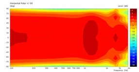
That's a good summary and I agree with it. Just a few more models to see it all the predictions/expectations hold true. I can include off axis as well, the polar graphs are +/-90 deg but they are normalized to 0deg.
That can be easily done. It's a near ideal flat membrane. BTW I'm interested in whether planars can reduce floor bounce because they are suppose to have narrow vertical polars and wide horizontal polars. This asymmetry may help spread diffraction if mounted in a torus.
The cone's rear magnet is not a major issue unless you want a clean non diffracted rear field. My understanding is the rear field will get reflected/diffraction anyways from the room.
Perhaps SL wasn't interested because he didn't consider diffraction from the baffle edge an audible issue, many others do. I propose that it is a viable option and probably superior to the alternative of spreading the diffractions around the edge of a flat baffle of any shape.
He did some work on reducing it in the LX521 baffle shape. BTW thanks for starting the thread ScottJ it has been a very interesting set of experiments for me.
But let me say that the Torus shape doesn't seem to be a great solution for a "midwoofer" type driver because the shape causes other problems. In the "pros" column the relatively large radius of the curved surface of the torus will smear out diffraction. But in the sims I still see the "oscillations", so it's only partially effective at that. Another "pro" is that the torus shape is, at the same time, increasing the front-to-back pathlength, so you will get less loss at "low" frequencies. In the cons column, I see some problems in the "throat" especially to the rear where the driver magnet and basket (potentially, it wasn't part of the model). I would really like to see line plots of on axis and several off axis angles out to, say, 75 degrees. Another "con" is that the torus is going to be physically large, and its size will prevent other drivers from being placed nearby.
That's a good summary and I agree with it. Just a few more models to see it all the predictions/expectations hold true. I can include off axis as well, the polar graphs are +/-90 deg but they are normalized to 0deg.
Loading the Neo3 into the torus would help to extend its usable range downwards, and no other driver would be needed for higher frequencies so spacing might not be an issue. I'm not sure if that has been discussed already in this thread but it might be worth modeling
That can be easily done. It's a near ideal flat membrane. BTW I'm interested in whether planars can reduce floor bounce because they are suppose to have narrow vertical polars and wide horizontal polars. This asymmetry may help spread diffraction if mounted in a torus.
The cone's rear magnet is not a major issue unless you want a clean non diffracted rear field. My understanding is the rear field will get reflected/diffraction anyways from the room.
This was actually a small part of my idea too. It's interesting because it highlights what are the supposed advantages of an OB and/or dipole speaker anyway.It would seem that if you wanted a more perfect dipole, you would use 2 drivers (monpole) back-back and control the phase of the rear driver to keep the forward wavefront in phase for the LF-MF range. The phase characteristic would be dependent on the baffle size and freq. It would also remove the simple solution elegance of a single driver dipole. 🙂
He did some work on reducing it in the LX521 baffle shape.
Reading the last section headed "From F3 to LX521" here LX521 Description it seems to me it's more about pattern control than concern over the audibility of the diffractions?
🙂 I'm glad you are enjoying it. I wish I had the tools and the knowledge to use them you have and am pleased you are here to do the hard work (It would be for me!) The ripple tank sim was very fiddly and the scale was almost useless, the best bit was the visual representation of how and where the waves were interacting.BTW thanks for starting the thread ScottJ it has been a very interesting set of experiments for me.
^ScottJ
I should actually build an OB and listen to it. I suspect it would sound like an omnidirectional speaker I built. I enjoyed it and was not traumatized by reflections.
I had read an article (of course I can't find it) where SL commented on the unusual baffle shape and seem to remember it was a minimalist design to control diffraction. It does have alot of irregular angles and side lengths to smear the diffraction and make the FR smoother.
I don't mind putting in some hrs to help me understand how these things work and even better to share it. ABEC/AKABAK is a great tool for "sand boxing" an idea. Its a substantial learning curve because you also need a CAD tool and meshing tool in order to build to models.
Last edited:
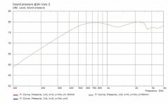
This is another torus, with a reduced OD=300mm and T=80mm. The LF rolloff freq has increased and the first peak is at a higher freq. The field shapes are the same as the previous
.
.
Attachments
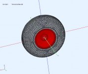

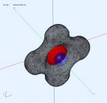
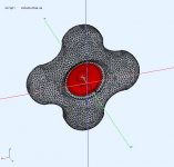
This modified perimeter with the "petal" arrangement. I would prefer odd #petals but used even numbers instead to get 1/4 symmetry for reduced simulation time. The petals vary from 300mm to 450mm, so that's 2xDriver to 3xDriver diameter. It can be compared to the previous torus sims.
The last pic has the 3 designs overlaid to compare them.
.
The last pic has the 3 designs overlaid to compare them.
.
Attachments
-
 Petal-ObsField@3K4Hz.jpg32.6 KB · Views: 111
 -
 Petal-ObsField@2K3Hz.jpg33.1 KB · Views: 101
 -
 Petal-ObsField@1KHz.jpg33.1 KB · Views: 101
 -
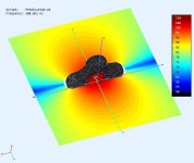 Petal-ObsField@300Hz.jpg31.5 KB · Views: 116
 -
 CustomPetalV2a-Polar@3m.jpg25.9 KB · Views: 125
 -
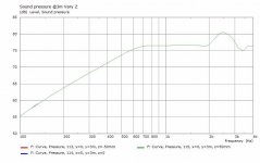
 CustomPetalV2a-FR@3m.jpg33.3 KB · Views: 136
 -
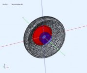
 CustomPetalV2a-RearView.jpg62.4 KB · Views: 123
 -
 CustomPetalV2a-FrontView.jpg66.7 KB · Views: 327
 -
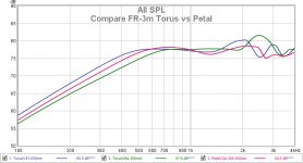 Compare FR-3m Torus vs Petal.jpg71 KB · Views: 143
Last edited:
Can I ask little OT: With what software you are drawing this bodies for Akabak? Are you using 2 subdomains, exterior and interior in Akabak for this torus simulations?
Last edited:
I use FreeCad + Gmsh and it's a single subdomain (that's usual but it works for shallow open designs like this).
I remember your omni project 🙂 A good dipole would sound very similar. Simpler OB's (and I include the torus) maybe not so much due to asymmetry and less than ideal polar response, I don't know how much this would matter in a "normal" listening position.I should actually build an OB and listen to it. I suspect it would sound like an omnidirectional speaker I built. I enjoyed it and was not traumatized by reflections.
The omni "sprayed" the room indiscriminately and I kept them 1.3m (7ms reflection) from the walls and they had no problem with soundstage and imaging. The only issue I had was getting them to sound clean when they were loud (100dB) otherwise very easy to listen to. So I wonder what an OB would sound like.
Your last couple of sims are interesting, particularly the lucky clover. At HF it looks as if there are effectively two polar patterns superimposed, a good demonstration of what happens with a varying baffle shape?
Combine the last two sims and you end up with Mattes' "flaffle" 😀
I have Jordan Eikona VTL with a removable rear panel, I'm tempted to make a baffle profile I can attach.
I have Jordan Eikona VTL with a removable rear panel, I'm tempted to make a baffle profile I can attach.
Last edited:
- Home
- Loudspeakers
- Full Range
- Did Siegfried Linkwitz miss a trick?