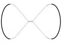
I did some crude photo editing to put two of those, back to back and close up the side. This would probably be pretty large, e.g. at least 18 to 24 inches wide so that the throat is large enough to accept a 4" or 5" driver. Maybe a ScanSpeak 10F fullrange or similar. Keep in mind that I have zero experience or knowledge of horn or waveguide design! The image was lifted from a web page on the oblate spheroid profile. I think it is mostly a strait (conical in this case) horn with an oblate profile to the lip roundover.
My cartoon is attached. I am calling it a "dogbone dipole" waveguide.
My cartoon is attached. I am calling it a "dogbone dipole" waveguide.
Attachments
Last edited:
That's right, https://www.diyaudio.com/forums/mul...od-diffraction-baffle-edge-7.html#post6372060 , it's interesting to see how far it can be pushed.I know you are interested in investigating this "torus" shape, but that might not be a useful profile above e.g. 2kHz no matter what you do.
I know you are interested in investigating this "torus" shape, but that might not be a useful profile above e.g. 2kHz no matter what you do.
Can you simulate other cross-sections that are rotated around the central axis to create the solid shape? I would be interested to compare the torus results to more waveguide or horn profiles. Where the inner surface end (e.g. the termination of the horn lens) you would just join to the other termination (e.g. front to rear) using some kind of gentle roundover.
Like two of these, back to back and joined together at the edges of the guide:
You will probably end up with something that is more like a cylinder with bulging sides and a horn in each end.
I'll kick the torus "can" a little more before moving on to other shapes. 🙂
The shapes were created in FreeCad and rotating curves (drawings) to solid is easy. Your drawing looks like an OSW. Is that what you intended?
Edit add : yes, I just read your second message
Last edited:
I did some crude photo editing to put two of those, back to back and close up the side. This would probably be pretty large, e.g. at least 18 to 24 inches wide so that the throat is large enough to accept a 4" or 5" driver. Maybe a ScanSpeak 10F fullrange or similar. Keep in mind that I have zero experience or knowledge of horn or waveguide design! The image was lifted from a web page on the oblate spheroid profile. I think it is mostly a strait (conical in this case) horn with an oblate profile to the lip roundover.
My cartoon is attached. I am calling it a "dogbone dipole" waveguide.
The OSWG magic is that little curvature in the throat. The rest is "conical" and it does not specify mouth termination. @mabat has a calculator that generates modified OSWG profiles that might be useful at higher freq but would not have pattern control at <1K for a horns of this size. Conical is close enough to test an idea. Thanks.
Yes, and from my amateur playing around, it seems it can be quite shallowConical is close enough to test an idea. Thanks.
The OSWG magic is that little curvature in the throat. The rest is "conical" and it does not specify mouth termination. @mabat has a calculator that generates modified OSWG profiles that might be useful at higher freq but would not have pattern control at <1K for a horns of this size. Conical is close enough to test an idea. Thanks.
I am not sure about how necessary the throat "curve" would be if the source is large, e.g. 4".
Anyway, much like a large diameter CD on a horn, it will probably not work well above some frequency, e.g. 10kHz. But if you can get it to work up that high, you can transition to a forward only tweeter above that point.
It's relative to the throat diameter (starting point) which is just slightly bigger for a woofer 🙂 I've done them before. I'll add a generous roundover.
Poking around some nether reaches of the web I came across this image. Too bad it is stuffed into a corner. This is a front firing horn and a dipole woofer array in a front-only waveguide. Something like this on both sides, perhaps? See, things are getting L A R G E fast.
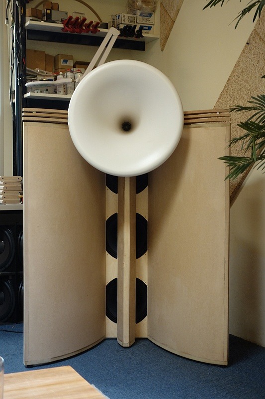
Image obtained from HERE.
Image obtained from HERE.
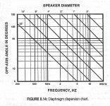
The directivity of a cone is mostly a function of its diameter, so it gets modeled properly. When you look at the previous polars you can see the beamwidth start to narrow after 1Khz. This chart is the ideal case for a simple cone (no inner whizzer cones).
.
.
Attachments
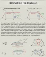
More about radiation by Klippel. A dome vs. planar vs. cone are all different! Cones have same pain as with dipoles, there is certain difficult range where radiation is not linear
https://www.klippel.de/fileadmin/_migrated/content_uploads/KLIPPEL_Sound_Radiation_Poster_01.pdf
https://www.klippel.de/fileadmin/_migrated/content_uploads/KLIPPEL_Sound_Radiation_Poster_01.pdf
Attachments
Rather than go too far down the horn road, a lossy torus seems to have potential when it comes to taming HF, the LF should still largely see it.
More about radiation by Klippel. A dome vs. planar vs. cone are all different! Cones have same pain as with dipoles, there is certain difficult range where radiation is not linear
https://www.klippel.de/fileadmin/_migrated/content_uploads/KLIPPEL_Sound_Radiation_Poster_01.pdf
Thanks for the paper. I agree, at higher frequencies the sim will not be accurate so I stay in a freq range below where the issues start.
The BEM sim assumes a rigid vibrating membrane, and its shape (flat, cone,dome,etc) is physically modeled. So radiation patterns will depend on the shape.
Am I wrong in assuming that, whether one starts with a conical horn and then starts to optimize for a specific target in dispersion, or that one starts at the other end of the spectre with a torus, at the end of the day you will end will up with a similar design in terms of horn/waveguide profile and roll back? So the torus experiment here is sort of the same as the experiments Mabat is doing in his horn profile thread, but using a very different starting point?
The priority isn't dispersion or constant directivity. The idea was to find another way to deal with the on axis peaks and dips of a "simple" open baffle speaker other than spreading the diffractions from a, for example, rectangular baffle.
The smearing of the diffractions around the "edge" of the torus appear to work well at low to mid frequencies, a simple, shallow conical waveguide may be able to push the useful range higher, or may not be necessary at all due to driver beaming.
The smearing of the diffractions around the "edge" of the torus appear to work well at low to mid frequencies, a simple, shallow conical waveguide may be able to push the useful range higher, or may not be necessary at all due to driver beaming.
Last edited:
Exactly, and why I'm suspecting that only the woofer front exit needs to be refined. The rear cone field is unavoidably diffracted due to the magnet.
Perhaps the driver could be moved back to allow more breathing space at the rear and more space for contouring the front exit.
- Home
- Loudspeakers
- Full Range
- Did Siegfried Linkwitz miss a trick?