jdrouin,
Your schematic in Post # 479 has some very wrong values.
Voltages, resistances, or both.
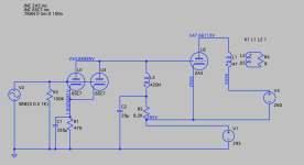
2A3 self bias resistor is 130 Ohms
342V - 335V gives Only 7V bias across 130 Ohms. That would be 54mA, but . . .
592V plate to 342V filament is 250V p-f.
A 2A3 with 250V p-f, and Only 7V bias would cause 250mA plate current. OUCH!
Please correct the schematic to working voltages and currents.
Your schematic in Post # 479 has some very wrong values.
Voltages, resistances, or both.
2A3 self bias resistor is 130 Ohms
342V - 335V gives Only 7V bias across 130 Ohms. That would be 54mA, but . . .
592V plate to 342V filament is 250V p-f.
A 2A3 with 250V p-f, and Only 7V bias would cause 250mA plate current. OUCH!
Please correct the schematic to working voltages and currents.

Using stacked power supplies the mixed bias (fixed bias due U1+U3 anode current via L3 and R5//C5 bias) IMHO is unnecessary.
Series resistor with L3 (AC decoupled to ground with few ten uF capacitor) performs the same ... and always problematic R//C in cathode is omitting.
Series resistor with L3 (AC decoupled to ground with few ten uF capacitor) performs the same ... and always problematic R//C in cathode is omitting.
My mistake . . .
It appears I missed (did not notice) the 35V drop across the plate choke, L3, of the input tubes.
Yes, 2A3 bias is 42V.
It appears I missed (did not notice) the 35V drop across the plate choke, L3, of the input tubes.
Yes, 2A3 bias is 42V.
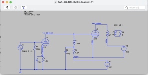
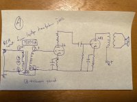
Euro21, did you mean something like this? The attached screenshot has the 6SC7 running at about 250V/4mA and the 2A3 at roughly 250V/60mAUsing stacked power supplies the mixed bias (fixed bias due U1+U3 anode current via L3 and R5//C5 bias) IMHO is unnecessary.
Series resistor with L3 (AC decoupled to ground with few ten uF capacitor) performs the same ... and always problematic R//C in cathode is omitting.
Attachments
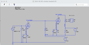
More playing around with choke-loaded, direct-connected and a stacked power supply. I read back through the discussion of DHT input/drivers in this thread and modeled circuits for 26 (140V/5.5mA) and 10 (350V/16mA) into 2A3 (250V/60mA).
Input sensitivity in both is 5V, so either one would need the 1:4 input transformer as discussed earlier.
This amp would mainly be playing digital sources:
So I'm wondering what impedance would be best in an input transformer.
Input sensitivity in both is 5V, so either one would need the 1:4 input transformer as discussed earlier.
This amp would mainly be playing digital sources:
- Sony CA70ES CD player with 2V / 50Kohm output
- DAC with 2V / 625 ohm output (Denafrips Ares II)
- MacBook Pro 13" with load impedance detection and adaptive voltage output, plus onboard DAC that can handle 96kHz sampling rate.
So I'm wondering what impedance would be best in an input transformer.
- Hammond 1140-LN-C lists its impedance ratios as 2.2K:36K and 600:10K
https://www.hammfg.com/part/1140-LN-C
- Cinemag CMLI-10-600 is 600:10K
https://cinemag.biz/line_input/PDF/CMLI-10-600.pdf
Attachments
Last edited:
Yes, I thought so.Euro21, did you mean something like this? The attached screenshot has the 6SC7 running at about 250V/4mA and the 2A3 at roughly 250V/60mA
"So I'm wondering what impedance would be best in an input transformer."
Using 600R input transformer is the challenge for previous stage.
If it's SS device with few hundred Ohm output impedance it can work well. Arbitrary tube output device may cause a problem.

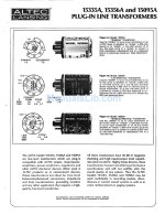
Does anyone have experience with Altec 15095A input transformers? Can be configured for 600:15K (1:5), and might be usable to connect 600 ohm source (DAC, laptop) to the grid of 26 or 10/10Y.
https://www.ebay.com/itm/225945901901
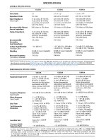
The old manual I found online (attached images) describes it as a "Bridging/Matching Transformer: Use the 15095A: 1) as an input transformer in an ALTEC mixer to "bridge" a 600-ohm source; 2) as an input transformer in an ALTEC power amplifier to "match" a 600-ohm source; 3) at any line-level point in a system to convert a 600-ohm or 150-ohm balanced or unbalanced line to a 15k-ohm line."
Looks like it should provide enough bandwidth. Any drawbacks to using something like this?
Online sales are typically $200 USD per pair, but they can be found for less. Comparable in price to a new pair of Hammond 1140-LN-C, and about $50 more expensive than ordering a pair of new Cinemag 600:10K transformers.
https://www.ebay.com/itm/225945901901
The old manual I found online (attached images) describes it as a "Bridging/Matching Transformer: Use the 15095A: 1) as an input transformer in an ALTEC mixer to "bridge" a 600-ohm source; 2) as an input transformer in an ALTEC power amplifier to "match" a 600-ohm source; 3) at any line-level point in a system to convert a 600-ohm or 150-ohm balanced or unbalanced line to a 15k-ohm line."
Looks like it should provide enough bandwidth. Any drawbacks to using something like this?
Online sales are typically $200 USD per pair, but they can be found for less. Comparable in price to a new pair of Hammond 1140-LN-C, and about $50 more expensive than ordering a pair of new Cinemag 600:10K transformers.
Attachments
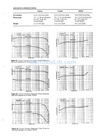
There is no miracle.
This Altec SUT represents technology limitations at that time where this device developed.
Not really "20Hz" compatible, at lower side the distortion is significant (core limitations).
At 20kHz the -47 degree phase shift doesn't mean much good.
See -for example- Jensen JT-6110K-B datasheet.
This Altec SUT represents technology limitations at that time where this device developed.
Not really "20Hz" compatible, at lower side the distortion is significant (core limitations).
At 20kHz the -47 degree phase shift doesn't mean much good.
See -for example- Jensen JT-6110K-B datasheet.
I suspect these Altec transformers were made by UTC as they look exactly like UTC P line, and have similar characteristics. In my experience, UTC O- and P-line transformers are OK, they have limitations at extreme audio frequencies, but what one would expect from such tiny transformers. They don't have sufficient inductance (compared to the more upscale A, HA, and LS input transformers). so LF distortion is relatively high. High frequencies are also compromised because self-resonance frequency is close to the top end (hence phase shift of 47 degrees at 20 kHz). I like how they obfuscate on measuring self-resonance frequency with secondary shorted, which is NOT how a transformer is used in real circuits.
Regarding Post # 486, If I am interpreting the Sony specification properly . . .
(Sony CA70ES CD player with 2V / 50k Ohm output); It can properly drive a 50k load.
Most 1:4 step up transformers do not have 50K Ohms primary impedance (and 50k x 16 = 800,000 Ohm secondary impedance).
(Sony CA70ES CD player with 2V / 50k Ohm output); It can properly drive a 50k load.
Most 1:4 step up transformers do not have 50K Ohms primary impedance (and 50k x 16 = 800,000 Ohm secondary impedance).
Thanks, euro21 and sser2, for your input. And thanks for your reading of the CD player spec, 6A3sUmmer.
After looking into it a little more, the Sowter 4383 (1:4, 600:10K) seems like a good option, and would be a similar price to the Hammond and Cinemag units mentioned above. It also claims to be usable for "600 ohms source 50K load."
https://www.sowter.co.uk/specs/4383.php
I'm a little concerned by what appears to be a slightly rising frequency response in the Sowter and Cinemag units, whereas the Hammond is dead flat. The Hammond phase shift, however, is 10 degrees at 20kHz, whereas Cinemag claims 5 degrees and Sowter does not appear to offer that info. Maybe I'm over thinking but these aren't exactly cheap little parts.
The Sowter 1475 is a better choice in my opinion. It's high impedance and can be used as 1:2 step-up. Using the 6N7 as driver tube it's plenty enough gain and an easy load is presented to the source. Not need to worry about special drive capabilities of the source.
https://www.sowter.co.uk/specs/1475.php
You get what you pay for. Considering the eternal life of a transformer the difference in cost is well worth the effort.
If want to save some money then use higher gain tube with 10K:10K input transformer like the Hammond 1140-LN-B. However the high inductance plate choke might become the bottleneck. Nothing wrong with using a plate resistor. More than choke vs resistor load the problem could be the low current of the driver. All things that need to be experimented. No simulator will give the answer.....
Last edited:
jdrouin,
A 10 degree phase shift at 20kHz in an amplifier that includes that transformer in a global negative feedback loop . . .
Might, or might not, cause oscillations (not very likely, unless the amplifier was poorly designed)
You quoted a specification of 10 Degrees phase shift at 20kHz.
Here is an Unusual way to consider that:
Sound velocity is 1080 feet / second.
1080 / (20,000 sine waves / second) = 0.054 feet
0.054 feet x 12 inches per foot = 0.65 inches
Drive both ofyour listening room speakers with a low level 20kHz mono sine wave.
Move one speaker 0.65 inches closer to your ears, versus the distance from the other speaker.
You just changed the phase of one speaker versus the other speaker by 10 Degrees.
If that is a problem . . .
Then sit at a precise listening spot, and have someone adjust your 2 speakers exact distances to be Much more accurate than 0.65 inches.
When improving my stereo playback systems . . .
I try to peel the outer layers off of the onion first, before I get to the less important inner layers which have far less important effects on the sound.
Double Blindfold Testing anybody?
Last edited:
jdrouin,
Have you built with a DHT triode driver yet?
If yes, please direct me to the Post # where you did that.
If not, this is a most frustrating thread.
Best, RC
Have you built with a DHT triode driver yet?
If yes, please direct me to the Post # where you did that.
If not, this is a most frustrating thread.
Best, RC
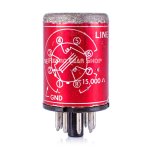
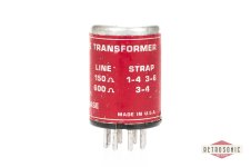
OK, I'm back with a newly built breadboard and in need advice on wiring an input transformer. I picked up a pair of Altec 15095A line input transformers for use with DHT driver stage, in this case 26 into 2A3.
I got all voltages dialed in on the new breadboard and then tried to play music but there is no sound. A laptop headphone jack connects to the amp input by RCA jacks (single-ended). Everything on the tubes seems to be connected correctly, so my guess is that the input trannies are where I've made an error.
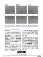
The attached pics show the 15095A pinout and the instructions on the can for wiring it 600R : 15K -- you strap pins 3 and 4 together. There are two versions of the wiring that I've tried. At first I had everything going to signal ground through the primary negative lead, so I thought maybe the input signal was getting shorted to ground. So I tried wiring the primary negative only to signal return, while the secondary negative goes to signal ground. Still no dice (pics attached):
A. Signal input hot to pin 1, signal output hot to pin 7. Pin 3 to pin 4 for the two primaries in series (600R). Pin 8 (secondary negative) connects to pin 6 (primary negative) and then signal ground. Pin 2 (internal shield?) to chassis ground).
B. Signal input hot to pin 1, signal output hot to pin 7. Pin 3 to pin 4 for the two primaries in series (600R). Pin 8 (secondary negative) to signal ground. Pin 6 (primary negative) only goes to signal return. Pin 2 (internal shield?) to chassis ground).
Any help would be greatly appreciated. Thanks!
I got all voltages dialed in on the new breadboard and then tried to play music but there is no sound. A laptop headphone jack connects to the amp input by RCA jacks (single-ended). Everything on the tubes seems to be connected correctly, so my guess is that the input trannies are where I've made an error.
The attached pics show the 15095A pinout and the instructions on the can for wiring it 600R : 15K -- you strap pins 3 and 4 together. There are two versions of the wiring that I've tried. At first I had everything going to signal ground through the primary negative lead, so I thought maybe the input signal was getting shorted to ground. So I tried wiring the primary negative only to signal return, while the secondary negative goes to signal ground. Still no dice (pics attached):
A. Signal input hot to pin 1, signal output hot to pin 7. Pin 3 to pin 4 for the two primaries in series (600R). Pin 8 (secondary negative) connects to pin 6 (primary negative) and then signal ground. Pin 2 (internal shield?) to chassis ground).
B. Signal input hot to pin 1, signal output hot to pin 7. Pin 3 to pin 4 for the two primaries in series (600R). Pin 8 (secondary negative) to signal ground. Pin 6 (primary negative) only goes to signal return. Pin 2 (internal shield?) to chassis ground).
Any help would be greatly appreciated. Thanks!
Attachments

Thanks. Are you saying both A and B should work?
To check the coil impedances -- using my laptop, I played a 1Khz test tone at 1V output. It measured as follows on my digital multimeter:
According to the Sowter FAQ Page, "The voltage ratio is the primary voltage divided by the secondary voltage you used. The primary impedance will be the ratio squared x the secondary impedance." The rated secondary impedance of the 15095A is 15K. So...
So, it would seem the rated ratio of 600R : 15K checks out.
Maybe I screwed up at the 26 tube. Will check tomorrow when I'm not tired.
I don't typically measure signal voltages, but now that you've got me doing it, I should measure the AC signal voltage while the amp is in operation, to see where it cuts out. Will try tomorrow when I'm not tired.
UPDATE: I was too curious, so I turned on the amp, did the 1V 1Khz test tone, and while the amp was running, there was virtually no AC signal at the same pins as above. I must have somehow introduced a short to ground, or something, up the signal chain?
To check the coil impedances -- using my laptop, I played a 1Khz test tone at 1V output. It measured as follows on my digital multimeter:
- Primary (pins 1 & 6): 0.473V
- Secondary (pins 7 & 8): 2.37V
According to the Sowter FAQ Page, "The voltage ratio is the primary voltage divided by the secondary voltage you used. The primary impedance will be the ratio squared x the secondary impedance." The rated secondary impedance of the 15095A is 15K. So...
- Voltage ratio: 0.473 / 2.37 = 0.1995
- 0.1995 x 0.1995 x 15,000 = 597.00375
So, it would seem the rated ratio of 600R : 15K checks out.
Maybe I screwed up at the 26 tube. Will check tomorrow when I'm not tired.
I don't typically measure signal voltages, but now that you've got me doing it, I should measure the AC signal voltage while the amp is in operation, to see where it cuts out. Will try tomorrow when I'm not tired.
UPDATE: I was too curious, so I turned on the amp, did the 1V 1Khz test tone, and while the amp was running, there was virtually no AC signal at the same pins as above. I must have somehow introduced a short to ground, or something, up the signal chain?
Last edited:
- Home
- Amplifiers
- Tubes / Valves
- Developing a 2A3 SET