Ian we are thankfull for your great work and effort in diy comunity.
But... why you always rotate your boards 90deg. It is impossible to do high quality streamer without some adapters as station pi. Why not design that you stack on Pi and have outputs from card on the same side as all pi connetors? Or i missed something?
I will like to do compact digital transport to feed my dac that has all inputs including hdmi.
Thank you Davorin
@androa76
Many of my new designs are already in that way.
https://github.com/iancanada/DocumentDownload
https://twitter.com/iancanadaTT

TransportPiAES by Ian, on Flickr

HdmiPiPro by Ian, on Flickr
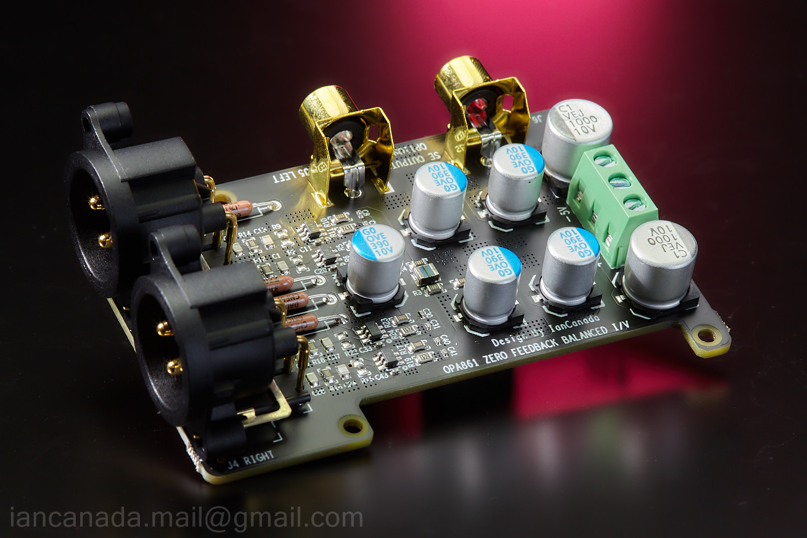
OPA861_1 by Ian, on Flickr
Ian
Many of my new designs are already in that way.
https://github.com/iancanada/DocumentDownload
https://twitter.com/iancanadaTT
TransportPiAES by Ian, on Flickr
HdmiPiPro by Ian, on Flickr
OPA861_1 by Ian, on Flickr
Ian

I have an Odroid with an isolatorPi so it seems to me best to go with the UcPi to provide power to the odroid. Anything on the isolated side of the IsolatorPi would require a seperate power supply. I could use an Allo Kali or an FIFO Pi Ultimate to feed my Soekris Dam 1021 DAC. Kali only takes 5V so I don't think the PurePi is the right option. Can the boards be removed from the metal frame, since it is not chassis friendly?
I have another system using the McFIFO/McDualXO combo. If I get a UCPureMkIII, can I use it to power both the McFIFO and the McDualXO board or would it be best to power them separately?
I have another system using the McFIFO/McDualXO combo. If I get a UCPureMkIII, can I use it to power both the McFIFO and the McDualXO board or would it be best to power them separately?
The manual says 4-5v AC should be used but the board says 9-12v AC on the bottom. Which one is right? I've been feeding 9v AC (measuring more like 10-11) but seem to have had charging issues.@stew1234 Yes, that voltage could be too high.
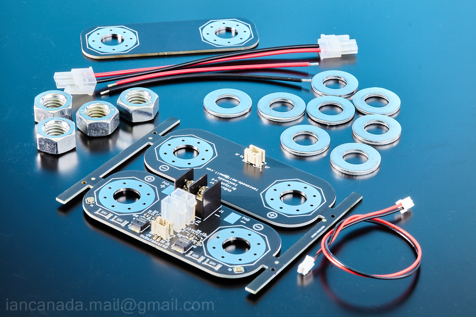
UcBalancer (#41F)
https://www.diyaudio.com/community/...fo-kit-group-buy.207438/page-240#post-7385114


Ian
https://www.diyaudio.com/community/...fo-kit-group-buy.207438/page-240#post-7385114
Ian
Attachments
So does Sync mode on UcPure MkIII work with mcFifo and all FifoPi’s or just Q7? It appears to use the mute signal which is prevalent on all of them.
Last edited:
I have Audio gd dac that not need mclk. What transport card with hdmi do you suggest?
Thank you.
Thank you.
Hi Ian,
I'm going to post my current LiFePO4 MKII Flagship config in September with some supporting photos and diagrams.
I think it's configured only utilizing only 1 side @ 5 x 3.3V = 16.5V. The other side is basically useless. In the future, I eventually want it to be configured @ 10 x 3.3V = 16.5V utilizing both sides.
I want to eventually power a PC:

In the future, I have to decide between replacing the ten Lithiumwerks batteries @ $80 or to use that $80 towards Eatons.
So, it would really help if we can convert the LiFePO4 MKII to use all ten slots @ 1 X 16.5V:

I'm in love with my UcPure/UcBalancer so deciding between UcPure/UcBalancer versus continuing with the LiFePO4 MKII Flagship will be really difficult:


If we can figure out 1 x 16.5V utilizing all ten batteries, it will help with my decision making in 12-24 months.
I'm going to post my current LiFePO4 MKII Flagship config in September with some supporting photos and diagrams.
I think it's configured only utilizing only 1 side @ 5 x 3.3V = 16.5V. The other side is basically useless. In the future, I eventually want it to be configured @ 10 x 3.3V = 16.5V utilizing both sides.
I want to eventually power a PC:
In the future, I have to decide between replacing the ten Lithiumwerks batteries @ $80 or to use that $80 towards Eatons.
So, it would really help if we can convert the LiFePO4 MKII to use all ten slots @ 1 X 16.5V:
I'm in love with my UcPure/UcBalancer so deciding between UcPure/UcBalancer versus continuing with the LiFePO4 MKII Flagship will be really difficult:
If we can figure out 1 x 16.5V utilizing all ten batteries, it will help with my decision making in 12-24 months.
G'Day @acg ,
I hope so. In theory it's designed for that flexibility, but it practice one easy config mistake with batteries can blow a fuse. Battery configs (Series and Parallel) are tricky if you are just a audio hobbyist like I not a true hardcore DIY'er.
I'm hoping to overcome the parallel barrier like I did with 1 x bank of five batteries for series.
Since I'm rusty, I have to re-read the manuals and re-learn how I got to my current config. I'll post as I'm re-learning as I hope to recall the steps that were taken.
I don't want to end up with spaghetti wiring, so right now it's perfectly clean. By re-wiring, I want to keep it that way.
Since I like to re-purpose my gear, it's difficult to plan how my primary and secondary and secondary primary rigs will play out in the future.
For example, my Intel NUC just stopped reading the mSATA drive so I can use the LiFePO4 MKII to power the NUC if there's a need. Intel NUCs make wonderful Audiophile devices by just booting off a USB stick, load entire OS into RAM, unplug USB stick. The Intel NUC was never in the audio cards, but now that's it's breaking down I may have to re-consider.
For now, the LiFePO4 MKII is powering Andrea's clock. I plan to upgrade to UcPure/UcBalancer in the future. So planned obsolence for LiFePO4 MKII is to power a PC one day. But maybe the better game theory play is to archive the LiFePO4 MKII and just move on from batteries and build multiple 12V+ UcPure/UcBalancer. Difficult to plan, but want to maintain future flexibility.
But re-purposing LiFePO4 MKII by refreshing ten new batteries @$80 versus $800 for a UcPure/UcBalancer Eaton 15.5V rig sounds mighty attractive right now if it's just powering a PC. In order for this option to work, I need to figure out 2 x banks of five batteries so it can help me weigh options.
I'll post my current config in a few weeks. Maybe, someone might have insight for a audio hobbyist on the wiring scheme. It may be something obvious I overlooked. I asked Ian, but he's super busy and my time-frame is 12-24 months away. So by posting, the light bulb might go off for Ian or someone else once they get a big picture of my current config over a long time-frame.
Last edited:
@Drive Shaft Just connect both positive wires to the positive side of your connector and both negative wires to the other. You now have 16.5V with double the energy storage.
For one of my applications I have three LiFePO4 boards stacked with a single 22V output and a lot of energy storage . They are so flexible...you can plenty of things with them not listed in the manual.
For one of my applications I have three LiFePO4 boards stacked with a single 22V output and a lot of energy storage . They are so flexible...you can plenty of things with them not listed in the manual.
Many thanks for your invaluable advice acg. The LiFePO4 is an extremely niche device so it's much appreciated, Cheers.
I just can't experiment much with batteries because there's no redo without buying replacement batteries or fuses and there's risk:
So I try to be extremely careful and do due diligence. Here's my config for 5 batteries @ 16.5V for 1 out of 2 sides:

I'm assuming this is what you are doing? It's a great option for more hours usage like if you are powering a power-efficient PC. Wow, 22V. I can't even grasp around how that could be done. Fortunately, the most I will ever need is 16.5V.
I'm able to easily get 8 hours on timer shutdown with Andrea's clock and one side. Curious how long I can get with parallel.
So this is how Ian help me combine the 13.2V rail and the 3.3V rail to get to 16.5V per side:

J1+ && J4- output === My DC 2.5mm plug
I'm guessing J1- && J4+ === combining 13.2V && 3.3V (in series) rails on one side
I'm guessing J2- && J3+ === combining 13.2V && 3.3V (in series) rails on the other side
I never tried the output of J2+ && J3-, but I'm assuming it should output 16.5V if I wanted another DC 2.5 plug, etc.
For jumper wires, I think I use "None" to get to 13.2V.
So J1+ && J2+ gets me parallel along with J4- && J3-?
Again, no hurry. Also, I'll try to run it by Ian for his approval before implementing.

I just can't experiment much with batteries because there's no redo without buying replacement batteries or fuses and there's risk:
2. All battery cells are internally connected together in parallel on the PCB. You must never reverse the positive and
negative terminals when assemble/solder them into PCB. Reversing battery terminals could be very dangerous.
So I try to be extremely careful and do due diligence. Here's my config for 5 batteries @ 16.5V for 1 out of 2 sides:
Mine is a Ian-approved and Ian-helped-configured 16.5V rail. So both rails are configured for 16.5V. Just, I guess, need to parallel both rails.Two 3.3V-13.2V battery direct isolated voltage rails for analog section and other sensitive circuits. Each of
the rails can be configured as 3.3V, 6.6V, 9.9V or 13.2V separately.
Multiple LifePO4 power supplies can be bridged together to get more voltage rails.
I'm assuming this is what you are doing? It's a great option for more hours usage like if you are powering a power-efficient PC. Wow, 22V. I can't even grasp around how that could be done. Fortunately, the most I will ever need is 16.5V.
I'm able to easily get 8 hours on timer shutdown with Andrea's clock and one side. Curious how long I can get with parallel.
J1: 3.3V pure battery output voltage rail in 2-pin 5.0mm terminal
J2: 3.3V pure battery output voltage rail in 2-pin 5.0mm terminal
J4: 13.2V/9.9V/6.6V/3.3V pure battery output voltage rail in 2-pin 5.0mm terminal
J3: 13.2V/9.9V/6.6V/3.3V pure battery output voltage rail in 2-pin 5.0mm terminal
So this is how Ian help me combine the 13.2V rail and the 3.3V rail to get to 16.5V per side:
J1+ && J4- output === My DC 2.5mm plug
I'm guessing J1- && J4+ === combining 13.2V && 3.3V (in series) rails on one side
I'm guessing J2- && J3+ === combining 13.2V && 3.3V (in series) rails on the other side
I never tried the output of J2+ && J3-, but I'm assuming it should output 16.5V if I wanted another DC 2.5 plug, etc.
For jumper wires, I think I use "None" to get to 13.2V.
Just connect both positive wires to the positive side of your connector and both negative wires to the other. You now have 16.5V with double the energy storage.
So J1+ && J2+ gets me parallel along with J4- && J3-?
Again, no hurry. Also, I'll try to run it by Ian for his approval before implementing.
Last edited:
Hi@dvb projekt
You can not use the two 3.3V rails for the 6.6V output. So, you can parallel the rest two 6.6V rails together. In this case, 4 cells will be needed.
Regards,
Ian
An old Post, so not sure, if still correct with mk3.
I have put the two single 3.3 in series to get the 6.6V and it seems to work… any problem I don‘t see?
Thx
Christian
Hi

Is this OK or is there any Problem. In my understanding the 3.3V are completely isolated, so it should work... but maybe there is something i miss?
Thx
Christian
Is this OK or is there any Problem. In my understanding the 3.3V are completely isolated, so it should work... but maybe there is something i miss?
Thx
Christian
Yes, M12.

https://www.mcmaster.com/products/s...nt~metric/for-screw-size~m12/material~copper/

I believe it's been confirmed the pitch thread is 1.75mm for the Hex Nuts along with M12.
I recommend to consider on doubling up washers on the UcBalancer PCB side as the +- on the back of the Main Terminals of the UcBalancer touches the Eaton if only single washer used. Although, I believe it only touches the plastic coating on the Eatons. Also, I think you can cut off the excess on the back of the UcBalancer Terminals, but since I like to play it safe and I had extra Cooper Washers that's what I'm rolling with this time around.

When I build my 15.5V in 2025, I'm going to try to order Custom Cooper Washers that are thicker from Machinists:


https://www.mathews-engineering.com/store/p13/Copper_Straps_for_Maxwell_Ultra_Capacitors.html
On this site, it displays two size options: M8 and M12. So I'm assuming these two size are pretty standard for Ultra Capacitors.
M12 all the way for Eatons.
https://www.mcmaster.com/products/s...nt~metric/for-screw-size~m12/material~copper/
I believe it's been confirmed the pitch thread is 1.75mm for the Hex Nuts along with M12.
I recommend to consider on doubling up washers on the UcBalancer PCB side as the +- on the back of the Main Terminals of the UcBalancer touches the Eaton if only single washer used. Although, I believe it only touches the plastic coating on the Eatons. Also, I think you can cut off the excess on the back of the UcBalancer Terminals, but since I like to play it safe and I had extra Cooper Washers that's what I'm rolling with this time around.
When I build my 15.5V in 2025, I'm going to try to order Custom Cooper Washers that are thicker from Machinists:
https://www.mathews-engineering.com/store/p13/Copper_Straps_for_Maxwell_Ultra_Capacitors.html
On this site, it displays two size options: M8 and M12. So I'm assuming these two size are pretty standard for Ultra Capacitors.
M12 all the way for Eatons.
Last edited:
Thank you for the presentation🙂
You will use the UcBalancer in place.When I build my 15.5V in 2025
You will use the UcBalancer in place.
I already have a UCPure MKI for my 15.5V for 2025, but I will need to procure 3 more UcBalancers in 2025.
This Summer, I built UcPure MKI / UcBalancer 3.3V and UcPure MKII / UcBalancer 5V.
Ian made it very DIY-friendly.
I remembered the size as the Matthew Engineering Buss Bars were procured years ago.
I have been preparing for years as I pre-ordered Eaton Balance Boards but Supply Chain is an indefinite wait. So I was very relieved when Ian released the UcBalancer. Life Saver.
I just recently learned the Thread Size is 1.75mm for the Hex Nuts. I didn't have the option as the Plastic Nylon Hex Nuts only offered one Thread Size, but if you stumble upon the Thread Size Pitch option, it's 1.75mm.
- Home
- Amplifiers
- Power Supplies
- Develop ultra capacitor power supply and LiFePO4 battery power supply