I had the same a few months ago in my basement system. My PCB was quite dusty and had some corrosion signs so I bathed it in cleaner (carb clearer was what I had to hand) gave it a decent scrub with a stiff ESD safe brush while wet and let it dry. To my surprise it’s b en working fine since. I wish you the same luck
I've since built the UcPure III using 2.7V Tecate batteries and can answer my own question. I measure output at 5.18V, so it luckily falls under the 5.25V limit some audio companies (e.g. Chord) specifies for equipment requiring "5V." I haven't built it with 3V batteries, and I've seen reports of 5.28V output with 3V batteries, but who knows if this is due to the battery voltages, battery brand, or circuit.If UcPure III is assembled using 2.7V batteries instead of 3V, will the output voltage be lower than using 3V batteries (5.28V output)?
For those of you that have tried 2xUcPure as a bipolar power supply for R2R DAC chips, what was your experience? Any issues with the voltage drop during the discharge/charge cycle? Did you like/keep it for this purpose?
Hello everyone,
I must be blind, however I am unable to identify the R015 resistors on LIFEPO4 MKIII. Can anyone point out where are they located?
It looks that I am unable to charge. Any other ideas beside replacing R015 are welcome.
I have a configuration for 2x3.3V, 1x 6.6V and 1x 9.9V. I use LDOVR LT3045-1A0G and LT3045-1A5IO LDOs to 5V from J3 and J4 to power StationPi PRO.
Attachments
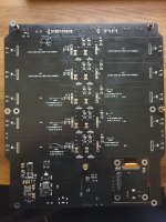
The yellow-ish resistors labeled '0592' are in those positions. I cannot easily get to the bottom of the MkIII I have here (they are mounted), but here is a picture of the bottom of my original (now dead) MkI showing those resistors marked.
Not sure why and when Ian changed the value. IF you have a meter that reads sub-ohm values accurately you can try to measure them.
If you remove the LiPoFE4 cells (pull them if in holders, carefully unsolder and lift the outer tab one at a time to check the resistor for that cell if not) and check each for continuity.
If all have continuity, you likely have another issue.
Greg in Mississippi

Many thanks Greg. It looks that they measure well. So there must be something else.
I have noticed that the batteries discharge too much. If I load them with MC3000 first they load with 0.15 A for some time until MC3000 can load with 1 or 2A (they discharge to 2.5V or lower sometimes). I have a second set of new batteries also which behave in the same manner - therefore the batteries can be ruled out also.
@iancanada: any ideas what I could check next?
Not sure what an "MC3000" is & what the rest of that statement means. Can you clarify?
To help troubleshoot, can you provide the following:
- What you are using for a charging supply?
- What messages do you see or don't see that indicate a problem with charging?
- How the problem started? Was it there from when you setup and started using the LiFePO4 board? Or did it come on gradually or all at once? AND did you make any changes at or around the time the charging problem started?
- Where did you source the cells? Some problems have been traced to using substandard cells. To prevent problems like that I use cells that are new, tested, & certified by a reputable battery source in the US.
- Are there any other things associated with the problem that we should know, such as other troubleshooting that you've tried?
- Can you post pictures of the setup, focusing on the LiFePO4 board, the charging source, & what it feeds?
Greg in Mississippi
P.S. I believe Ian is unavailable for responding to questions at this time, based on his extended absence from this site.
Quick sanity check for the intelligentsia here. I'm wiring up a UCPure pack and using a SMPS to power it. I'm hoping to just use the J2 as a DC input rather than dealing with the hassle of wiring up a barrel connector. The impression I have is that the polarity doesn't matter using J2, but I can't find any examples of a build like that.
made a test omitting batteries with directly sun powrred class d amplifier
I have a 2x25 Watt class D amp with CS8673 chip.
It can take maximum voltage of 24 Volts.
I have a 60 watt solar panel with maximum open circuit voltage of 22 Volts.
Is it possible to power such an amplifier directly with a solar panel with maybe some filtering capacitor of several thousand uF? Or should filtering be omitted ?
I live in egypt here you have always sun and it never rains.
Anyone tried running a class D amp like this?
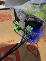
First test with some used LifePO4 mini, 6.6v in series to give ~13v output. Both units were pre-charged separately using a SMPS to charge them up quickly, but then I used a single battery power supply to power them on. I thought this would work because I measured 13v output prior to connecting to the load and all LED's/operation was fine, but when I connected it to the load I presume that because I used a single power feeder that the balancing failed (as there is no balancing between the two). I now have the lower 6.6v unit working, but the top one the power LED will not light (even when powered separately). Does the top one just need a new fuse or something?
Moving forward I'll always use two separate power supplies!
Moving forward I'll always use two separate power supplies!
Attachments
Last edited:
Not clear what you meant by a "single battery supply to power them on..."
Was it a single LiFePO4 cell?
Was it a single one of the SMPS supplies you used to charge them up?
Or something else?
& was it connected the AC or DC input & within the stated "AC 6V-12V or DC 9V-12V"?
& based on your description you had the 2 6.6V LiFePO4 Minis outputs wired in series while you had their inputs wired in parallel with a single supple, correct?
Section F of the instructions states "...Both AC and DC inputs have to be independent and cannot be shared with other devices." So you violated that if I understand how you had them wired & powered
Also I am not sure how the MOSFET devices used to connect the LiFePO4 cells both to the output & to the CC-CV charging circuit would react when running 2 of them in series.
Did the setup function at all hooked up the way you described & failed after some time? Or did it fail immediately?
Finally did you confirm this mode of operation with Ian before you tried it?
I can see a number of possible ways this could fail. Understanding exactly how you had it hooked up, what was powering it, & how it failed will help debug this.
But I am pretty sure this is not an intended or viable use-case for these.
Let us know.
Greg in Mississippi
Make the world best possible +/-5V UcPurePro ultracapacitor power supply
Talking about the best power supply, the first question would be what is the best power supply? The answer is already there: ideal voltage source.
An ideal voltage source is a two-terminal device that its output voltage keeps constant without any noise or changes. The ESR will be zero over 0Hz to infinity.
It can also supply unlimited current as long as there is demand. The dynamic transient response will be a flat straight line. However, in the real world, this thing doesn't exist.
Then the second question will be which is the power supply that is closest to an ideal power supply?
Let's look at the specification of a typical 3000F ultracapacitor XL60-2R7308T-R:
ESR:0.23mOhm@1kHz, Dynamic current: 2400A, capacity: 3000F
So I'd like to say the answer could be the ultracapacitor power supply because I can not find any other solution that is close to the ideal power supply as much as a huge ultracapacitor.
+/-5V is a very useful power supply for DAC applications, such as TDA1541, OPA861 I/V stage, and many other analog sections. Now, it's no longer difficult to build a world best +/-5V power supply using UcPurePro and 3000F ultracapacitors. That would be a very exciting project and only needs just a few steps.

UcPureProInatall1 by Ian
Step1: Install a 3mm thickness washer (or two 1.5mm washers) between each ultracapacitor terminal and PCB plate.

UcPureProInatall2 by Ian
Step2: Make sure all ultracapacitors are fully discharged. Install all the four ultracapacitors into the UcPurePro back plate PCB in right orientations as the marks. Then screw the four 12mm nuts to the terminals (not tighten). Metal self-locking nuts are highly recommended to ensure best connection and lowest ESR under high current. Never use plastic nuts because of the possible poor connections!

UcPureProInatall3 by Ian
Step3: Do the same as Step2 on the other side to assemble the UcPurePro front plate PCB to the ultracapacitor pack. Ensure no pins touch to the ultracapacitors at the both back side of the PCBs.

UcPureProInatall4 by Ian
Step4: Put the ultracapacitor pack assembly on a flat surface, ensure the five connection terminals to the UcPurePro main board are at the same side. Tighten all eight self-locking nuts using nut socket tool KIT. Cover all the nuts with matched isolation caps to prevent from possible short circuits.

UcPureProInatall5 by Ian
Step5: Install the UcPurePro +/-5V main board to the ultracapacitor pack terminals using the five 3mm spring washer screws. Ensure the screws are tightening. The last thing before finish the assembling job is to Install a PH2.0 control cable from the front plate to the J16 of the UcPurePro main board .

UcPureProInatall6 by Ian
Step6: Connect a 1182M12 (or a 1182L12 with secondary coils in parallel) 12V AC transformer to the J3. D3 will light up after the transformer is powered. If it is the first time of use, please wait an hour or so until the Full LED D8 is on. Then turn on the UcPurePro +/-5V power supply by the on-board or external ON-OFF switch, or by the control chain. The blue pure LED, and both D1 and D2 LEDs on the front plate will light up. Now, the world best +/-5V power supply is working and will be ready for your project.
In pure mode, the +/-5V output will be 100% isolated from the input so the common mode noise transmission path will be cut. The ground will be pure virtual ground with the ESR closed to 0, so no ground loop can be built.

UcPureProInatall7 by Ian
Note1: To ensure the ultracapacitors are fully charged before turning on, It's highly recommended to keep the AC input always connected.
Note2: UcPurePro was specially designed in low profile dimensions. There are many options to mount. It would be very nice if somebody could print a mounting bracket or case for it.
Talking about the best power supply, the first question would be what is the best power supply? The answer is already there: ideal voltage source.
An ideal voltage source is a two-terminal device that its output voltage keeps constant without any noise or changes. The ESR will be zero over 0Hz to infinity.
It can also supply unlimited current as long as there is demand. The dynamic transient response will be a flat straight line. However, in the real world, this thing doesn't exist.
Then the second question will be which is the power supply that is closest to an ideal power supply?
Let's look at the specification of a typical 3000F ultracapacitor XL60-2R7308T-R:
ESR:0.23mOhm@1kHz, Dynamic current: 2400A, capacity: 3000F
So I'd like to say the answer could be the ultracapacitor power supply because I can not find any other solution that is close to the ideal power supply as much as a huge ultracapacitor.
+/-5V is a very useful power supply for DAC applications, such as TDA1541, OPA861 I/V stage, and many other analog sections. Now, it's no longer difficult to build a world best +/-5V power supply using UcPurePro and 3000F ultracapacitors. That would be a very exciting project and only needs just a few steps.
UcPureProInatall1 by Ian
Step1: Install a 3mm thickness washer (or two 1.5mm washers) between each ultracapacitor terminal and PCB plate.
UcPureProInatall2 by Ian
Step2: Make sure all ultracapacitors are fully discharged. Install all the four ultracapacitors into the UcPurePro back plate PCB in right orientations as the marks. Then screw the four 12mm nuts to the terminals (not tighten). Metal self-locking nuts are highly recommended to ensure best connection and lowest ESR under high current. Never use plastic nuts because of the possible poor connections!
UcPureProInatall3 by Ian
Step3: Do the same as Step2 on the other side to assemble the UcPurePro front plate PCB to the ultracapacitor pack. Ensure no pins touch to the ultracapacitors at the both back side of the PCBs.
UcPureProInatall4 by Ian
Step4: Put the ultracapacitor pack assembly on a flat surface, ensure the five connection terminals to the UcPurePro main board are at the same side. Tighten all eight self-locking nuts using nut socket tool KIT. Cover all the nuts with matched isolation caps to prevent from possible short circuits.
UcPureProInatall5 by Ian
Step5: Install the UcPurePro +/-5V main board to the ultracapacitor pack terminals using the five 3mm spring washer screws. Ensure the screws are tightening. The last thing before finish the assembling job is to Install a PH2.0 control cable from the front plate to the J16 of the UcPurePro main board .
UcPureProInatall6 by Ian
Step6: Connect a 1182M12 (or a 1182L12 with secondary coils in parallel) 12V AC transformer to the J3. D3 will light up after the transformer is powered. If it is the first time of use, please wait an hour or so until the Full LED D8 is on. Then turn on the UcPurePro +/-5V power supply by the on-board or external ON-OFF switch, or by the control chain. The blue pure LED, and both D1 and D2 LEDs on the front plate will light up. Now, the world best +/-5V power supply is working and will be ready for your project.
In pure mode, the +/-5V output will be 100% isolated from the input so the common mode noise transmission path will be cut. The ground will be pure virtual ground with the ESR closed to 0, so no ground loop can be built.
UcPureProInatall7 by Ian
Note1: To ensure the ultracapacitors are fully charged before turning on, It's highly recommended to keep the AC input always connected.
Note2: UcPurePro was specially designed in low profile dimensions. There are many options to mount. It would be very nice if somebody could print a mounting bracket or case for it.
Last edited:
Thank you Ian for creating this. A lot of us been looking for your +/-5V UcPurePro ultracapacitor power supply, Ideal for the TD1. Looks great.
Love what I think are the fuses those are impressive great balance of protection and low ESR.
Love what I think are the fuses those are impressive great balance of protection and low ESR.
Auto fuses are first time being used by UcPurePro ultracapacitor power supply for much lower ESR and much higher reliability by comparing with the standard fuses.
Hello Ian,Make the world best possible +/-5V UcPurePro ultracapacitor power supply
Talking about the best power supply, the first question would be what is the best power supply? The answer is already there: ideal voltage source.
An ideal voltage source is a two-terminal device that its output voltage keeps constant without any noise or changes. The ESR will be zero over 0Hz to infinity.
It can also supply unlimited current as long as there is demand. The dynamic transient response will be a flat straight line. However, in the real world, this thing doesn't exist.
Then the second question will be which is the power supply that is closest to an ideal power supply?
Let's look at the specification of a typical 3000F ultracapacitor XL60-2R7308T-R:
ESR:0.23mOhm@1kHz, Dynamic current: 2400A, capacity: 3000F
So I'd like to say the answer could be the ultracapacitor power supply because I can not find any other solution that is close to the ideal power supply as much as a huge ultracapacitor.
+/-5V is a very useful power supply for DAC applications, such as TDA1541, OPA861 I/V stage, and many other analog sections. Now, it's no longer difficult to build a world best +/-5V power supply using UcPurePro and 3000F ultracapacitors. That would be a very exciting project and only needs just a few steps.
UcPureProInatall1 by Ian
Step1: Install a 3mm thickness washer (or two 1.5mm washers) between each ultracapacitor terminal and PCB plate.
UcPureProInatall2 by Ian
Step2: Make sure all ultracapacitors are fully discharged. Install all the four ultracapacitors into the UcPurePro back plate PCB in right orientations as the marks. Then screw the four 12mm nuts to the terminals (not tighten). Metal self-locking nuts are highly recommended to ensure best connection and lowest ESR under high current. Never use plastic nuts because of the possible poor connections!
UcPureProInatall3 by Ian
Step3: Do the same as Step2 on the other side to assemble the UcPurePro front plate PCB to the ultracapacitor pack. Ensure no pins touch to the ultracapacitors at the both back side of the PCBs.
UcPureProInatall4 by Ian
Step4: Put the ultracapacitor pack assembly on a flat surface, ensure the five connection terminals to the UcPurePro main board are at the same side. Tighten all eight self-locking nuts using nut socket tool KIT. Cover all the nuts with matched isolation caps to prevent from possible short circuits.
UcPureProInatall5 by Ian
Step5: Install the UcPurePro +/-5V main board to the ultracapacitor pack terminals using the five 3mm spring washer screws. Ensure the screws are tightening. The last thing before finish the assembling job is to Install a PH2.0 control cable from the front plate to the J16 of the UcPurePro main board .
UcPureProInatall6 by Ian
Step6: Connect a 1182M12 (or a 1182L12 with secondary coils in parallel) 12V AC transformer to the J3. D3 will light up after the transformer is powered. If it is the first time of use, please wait an hour or so until the Full LED D8 is on. Then turn on the UcPurePro +/-5V power supply by the on-board or external ON-OFF switch, or by the control chain. The blue pure LED, and both D1 and D2 LEDs on the front plate will light up. Now, the world best +/-5V power supply is working and will be ready for your project.
In pure mode, the +/-5V output will be 100% isolated from the input so the common mode noise transmission path will be cut. The ground will be pure virtual ground with the ESR closed to 0, so no ground loop can be built.
UcPureProInatall7 by Ian
Note1: To ensure the ultracapacitors are fully charged before turning on, It's highly recommended to keep the AC input always connected.
Note2: UcPurePro was specially designed in low profile dimensions. There are many options to mount. It would be very nice if somebody could print a mounting bracket or case for it.
It makes me feel good to see that my original idea in which I explained to you to use supercapacitors for best power supplies evolved a lot.
I wonder though why you did not try to build a +V only version which can be operated 24/7 without the need to charge inbetween since you allready have two banks available.
If using your ultracapacitor based power supplies, and using them in the so called Pure-mode, it needs recharging in off-time.
It only can be operated 24/7 if choosing the option to charge inbetween with the note that it's not galvanic separated from source power supply.
I mentioned it before, why not building a supercapacitor power supply based on two banks (which you allready have), one charging while the other is discharging? As I told you there are many Mosfets available with very low RDS-On which can be used to switch between charging bank and discharging bank.
Mosfets can do a much better job than conventional relays and do not suffer from switching noise like my first UC psu's with many relays on them did.
You only need a voltage sensing circuit which detects when voltage is too low to switch to charged bank.
Would you take in consideration to develop this kind of power supply? If yes, I probably would be the first to order a few from you.
Kindest regards,
Alex
This is an excellent idea, would be an amazing product. Ian, please consider!Would you take in consideration to develop this kind of power supply? If yes, I probably would be the first to order a few from you.
My UC Pure MKII has stopped supplying power. All four lights on the power supply suggest everything is working when turned on (red, yellow, green and blue) but when I measure the switched output and continuous output I am getting 0v. Any suggestions on what else to check? What should voltage across the fuse measure?
Looks like it was the fuse. I measure around 3.3v from the neutral input on the UCpure board (coming from the ultracaps) to one side of the fuse but get 0v on the other side of the fuse suggesting the fuse blew. Does anyone know the fuse part number?
- Home
- Amplifiers
- Power Supplies
- Develop ultra capacitor power supply and LiFePO4 battery power supply