Hi Carlos !
Nice to see your amps growing!
Also your attempt to get the brain free with a pretty women is quite promising. Amps only is killing creative minds. ...but... aren't you married? 😀
Take care or
Back to topic:
Your approach to skip the emitter resistors:
Which type of resistors did you use, when u noticed the negative influence? Wire wound? Did you also compare with low inductive types?
Nice to see your amps growing!
Also your attempt to get the brain free with a pretty women is quite promising.
Amps only is killing creative minds. ...but... aren't you married? 😀 Take care or
Back to topic:
Your approach to skip the emitter resistors:
Which type of resistors did you use, when u noticed the negative influence? Wire wound? Did you also compare with low inductive types?
The mind if free to apreciate the young girl beauty...of course i cannot advance
I am happy to met you here Choco...a very good old friend...i have your images in front of that German lake..near the mountains. It is very good watching you in another stage of your life...not so happy, as culture may be enormous problem...you may feel very lonely...for sure.
One of the ideas, about Dx amp, is to make something cheap.... the resistors easy to find in brazil (for future kit's production) are those wire wound ones...but they have six turns only...this is very small to disturb too much...was more punch in the bass what i have perceived clearly..without doubts....i have installed them once more and i perceived..also the meters turns slow (analog and digital AC voltimeters connected to output during musical reproduction....i have removed them finally, my conclusion is that they may be interesting as protection, as power equalizers when many output pairs is beeing used...but in this Ximple amplifier...negative...they were banished out of this amp.
Those non inductive beauties are expensive, and to produce here, the amplifier will have to be sold withing a competitive cost range compared to LM3775...if not, no way to convince Brazilians...no way.... my people may be not very well instructed with good schools, but they are clever....more clever than needed...and this sometimes create problems.
As exist some ideas to future business with this schematic, it have to use cheap dirty transistors, cheap parts, minimized parts quantity (more parts will be removed soon...regenerative may fly out!)..only those parts that affect clearly the sonics will be keept there...for instance...feedback capacitor is needed...Miller not needed....regenerative maybe not needed.... big condenser not needed for sure (with good supplies..but for kits...hummm...470uf may be needed..at least this small ones)
Sounded good Chocoholic...so good as Choco design i have made many monthes ago.
Life is good those days....and i am feeling better as you are here, in this thread, with me now....interesting how internet can create confidence and friendship connections.
I will take my Airplane to the frontier...extreme Northwest of Amazon... to testimony deviation of gas lines that are happening there if informs are correct..i will have to write some papers to Federal Government that are waiting those informs.
regards,
Carlos
hi
As I told, in post above ....
I would set up my version of Dx-Amp and do some tests.
***********************************************
This is the 'Greg Erskine' very nice schematic I used for my set up.
dxamp - greg version from 2007-02-14
http://www.diyaudio.com/forums/attachment.php?s=&postid=1134970&stamp=1171455661
My first testing of this amp have my small modifications ( already mentioned above),
and using other, but similar transistors ( some told by Carlos as good alternatives ).
I have also told, I have not all transistor types in my sim software.
I also used 'only' 2x30 V DC supply.
I do not need more power than this.
I would think Transformer: 2x22VAC, 200-300 VA .... for each channel
*********************************************
Results:
Very good!
* Upper frequency limit is ~200kHz
* THD distortion is very low. ( I must say I was a bit surprised )
* Fourier Analysis spectrum is also showing some nice things.
I will keep my version, for myself.
I would recommend anyone DIY, to try your own version of this Amplifier.
😎 You may be Pleasantly Surprised!
This is definitely a good audio amplifier, in my opinion.
Regards, lineup
Aha! I can see you recommend MJL15004...
I have a bunch of very nice sounding MJL21193/21194 with outputboards in need of a input/driver board
I will run them at +/- 50-55V
any problem with this
I have a bunch of very nice sounding MJL21193/21194 with outputboards in need of a input/driver board
I will run them at +/- 50-55V
any problem with this
I am also producing some Artistic board with real parts over it.
To show the amplifier, in a more real manner...but for sure will not be so pretty as Greg's work.
The full throttle thread has many images from the earlier models...called Ximple and Simplício..you can see test circuits there...made to listen...not to a beauty competition.
regards,
Carlos
To show the amplifier, in a more real manner...but for sure will not be so pretty as Greg's work.
The full throttle thread has many images from the earlier models...called Ximple and Simplício..you can see test circuits there...made to listen...not to a beauty competition.
regards,
Carlos
Attachments
... now we are all getting crazy about professional PCBs, - right?
I got infected end of last year.
Now you..
😉 😎
I got infected end of last year.
Now you..
😉 😎
I really think that those things are really foolishes.
Also i think that we are not professionals, we are hobbie guys and we do not need those things....to compete with professionals....waste fo time!...no money will enter to compensate your effort and you will have only the possibility to open the amplifier case to show the unit to your near friends.
Your friends may think that you made enormous effort to convince them that you are a professional..when you are not...ahahahaha.
A little bit ridiculous in my point of view...but there are hundreds that apreciate those things...they use to say that if you have to do something do it perfect.... they are programmed alike computers, they cannot think about the time losses because of that and many consequences that will produce inside friends mind..some ideas this behavior may produce can be not so nice..
At least he will not be considered a "pig" alike i am....ahahahahha.
If you search for "full throotle construction of amplifiers ", you will see that i do not bother with those things...i love to make them fast to listen them as soon as possible and finishing to construct another one...and another one...and once more..and repeat all that maniac behavior in the next week, month and year...... i am also fanatic and sick alike many folks...i am not exception....i am crazy inside my own way.
This is something i asked Greg Erskine, my dear friend, as i want to have people constructing, and i have failed related that as i am very bad to make Propaganda about my own things....the pretty board is to atract people to construct.
I am also constructing a pretty circuit, in the real world, to show how pretty this construction can be ...a non working circuit with pretty coloured parts only...as mine working things are ugly and do not make a nice presentation of the product.
I want to give a chance to myself to show some ideas to forum friends, and also to give them a chance to realise some ideas.
That "simple amplifiers can sound so good, or even better than sophisticated designs"...but i think people do not want to face this reality...that's what i am starting to believe, to conclude.
PCboard was made...copper lines layout, professional schematic provided, general informations offered, the chance to the one make his own version was offered too...but no one had intentions to construct till today...let's see the future.
When the first one construct and evaluate positive... a boom of guys will go to do also....this is a normal "mechanic" of human behavior.
Be sure, dear Choco, that all this is an effort to create some interest..pretty things are always well accepted..ugly things makes people think about ugly sound...ahahahaha...people is wonderfull!
Send me all ugly girls to scratch my back....to swim with me in my swiming pool and to watch television with me...i love ugly girls, they are in bigger quantity than the pretty ones..also the pretty ones are too much hunted.
BTW dear Chocoholic, tell us something about your adventure in Hong Kong.
You made me feel so idiotic doing professional boards...hehe..you cannot believe the effect on me...alike a punch on my chin, almost a knock out!...but i know your intentions were not that one...my own personal beliefs produced that punch into myself..relax man...i still apreciate you very much...you are not a standard German....much more kind than many others.
regards,
Carlos
You made me feel so idiotic doing professional boards...
hehe..
you cannot believe the effect on me...
alike a punch on my chin, almost a knock out!
Yeah,
destroyer X
You are now a professional!
So what are you doing here at the hobby diy audio forum???
😀
Not only there are people doing better PCB here.
There are also people trying to improve performance of circuits.
Let's remember one thing:
That not to fool ourselves
Saying we are amateurs
while trying to be professional
in our audio works
DIY Audio people, the real ones
should have audio circuits and audio things
that are like 50% good only.
😀
Thanks to ChocoHolic!
You did save one guy here, from turning bad
and going ProAudio.
It would have been a sad things for all of us
to miss him.
Regards
lineup
Re: I really think that those things are really foolishes.
Hong Kong?
Hong Kong would be much more my taste. But I am in Guangzhou. 3h far from Hong Kong. We only go to Hong Kong for some party week ends once and while. But you can also party in GZ area, believe me. Unfortunately most people here do not speak english, that's a little bit a fun killer.
Anyway ...visited Peking for a few days... Forbidden City, Great Wall etc.... impressive!
destroyer X said:
BTW dear Chocoholic, tell us something about your adventure in Hong Kong.
regards,
Carlos
Hong Kong?
Hong Kong would be much more my taste. But I am in Guangzhou. 3h far from Hong Kong. We only go to Hong Kong for some party week ends once and while. But you can also party in GZ area, believe me. Unfortunately most people here do not speak english, that's a little bit a fun killer.
Anyway ...visited Peking for a few days... Forbidden City, Great Wall etc.... impressive!
destroyer X said:i am crazy inside my own way.
Carlos,
you're a nut in any other way.
much more kind than many others.
If you look closely, most others are much kinder than you expected.
May be interesting also.... if they do not talk your language.
If i was in your place, for sure i would be having fun with language.... hummm, maybe not...they have that problem related respect....
When i was in Japan, Sony company sent a man to take care of me (now a days big director, he gave me the patent of some design alike mine made by Sony in the seventies)...and he told me that he was there to give me all my needs.
So i pointed the other side of the Airport...Narita was the airport, and i pointed a pretty yellow sport Mazda and i told him:
- "I want that one"...you cannot imagine how much telephone calls he gave to Tokyo till i told him i was kidding.
25 years latter i enter Sony to work.... he was the International Director...i receive an internal mail.
I want that Mazda!
regards,
Yoshida
Yeah Lineup...Choco had saved me from the tragedy to turn professional...hummm, the obligation, the have too, the need to work on it would kill my passion....i love freedom....imagine if you have to be with Catherine Zeta Jones all day long....say all day long, not a nigth meeting...all day long, continuously...imagine that!....have you got it?...torture!!!
Tell me Lineup, have my amplifier smashed your unit?...even showing bigger distortion in the simulator?... have you kicked the simulator .um?...tell me....tell me about stérile sounds that some CCS produces (not all...your own maybe not because my politics behavior)...tell me the audible noise when you switch your unit on...tell me...tell me...no one will listen our conversation..hehe...you can send direct message to avoid shame....have a photograph of the looser...that Lineupx...hehe.
When you compared your modified DX amp...the Linex amp with the original minimalist unit,..have you turn yourself green?
hehe...provocation may work...let's see.
If not constructed...you just cannot say the one is better...hehe...Simulator do not talk, do not evaluate...VIRTUAL!
regards,
Carlos
Attachments

I continue listening, testing, comparing and substituting parts.
The increase of the input coupling capacitor by a 10uf unit made the low end reproduction better.
The removal of the series input resistor turns treble more present.
The increase, in value, of the electrolitic condensers C3 and C6 to 1000uf produced increase in overall quality...bigger will be better, but board cannot accept that bigger size... stabilizing supply voltage, or the use off double independent supply result in sonic increase of quality.
The C10 increase to 1000uf resulted in more pretty bass...you may clamp with diodes to allow the use of lower voltage condensers, but do not forget diodes can detect Radio frequency and interferences..install small capacitors to ground to avoid problems...the inductance of bigger electrolitic condenser will not be an adequated low impedance patch to earth for those frequencies.
The quality increase result was not that enormous thing...in the reality not so clear to listen...and the amplifier cost increased substantially because of condensers cost.
But will add value to the amplifier.... sonic value.
C2, as we suspect, cannot be removed, zobel resistor turns hot, sound loss high end reproduction, dinamic goes and output turns hot...better value is 12 picofarads.
Degenerative, or regenerative resistors removed resulted nothing in sonics....they were keept there, as also not disturbing and 2 resistors cost are not a problem.
With those modifications the amplifier did not turn so different in all audio band...more focus on sonics, voices reproduction, when more than one singer is on the stage separate one related the other clearly...bass turn warm and more strong....and this is a problem, the speaker can burn easy...the bass punch is enormous....you will need a real 150 watts RMS speaker for 4 ohms use....those only painted as 150 watts..just numbers printed on them...will spit their coils out!
regards,
Carlos
lineup said:
lineup
PS. Did you get my ZelScope email, Carlos? DS
.
Carlos
my hot blooded friend with temperament
( I like that you also are honest, when telling me what I do wrong - in YOUR threads
This way I learn to be even more a gentleman ... not only in your topics.
🙂 )
---------
I am glad you have started this DX-AMP topic.
My opinion is, that this is one of your best Amplifier Projects
you ever have published at www.diyaudio.com !!!
I know you have learned some details from buying Hugh 'AKSA' Amplifier
and from the great support you have received from your good friend in Australia.
There are a few persons I listen very carefully to at this board.
Usually experienced 'oldies' like Nelson Pass & Hugh Dean.
There are plenty of better-wissers and those who knows everything
and they are not shy to tell how you should do and what is best audio circuit details.
But most of it is not as CREDIBLE and BACKED UP with years of practical experience.
Real Life Trial & Error validation, we may call it.
This is why 90% of these postings .... goes in one of my ears
😀 😀 and ..... out my other ear.
Not so, when a good old audio persons talk:
If you wake me up in middle of night ... I be able to quote a line
... from persons like Hugh Dean & Nelson Pass 🙂
😎 😎 😎 lineup at Lineup Audio Lab 😎 😎 😎
... knows a lot of good amplifier design details
... shared by best audio designers we have at our board
.....................................................
PS to Carlos:
.................................................................................................
16:56:50 - Sending file _carlos_files-from-lineup\zelscope-1.00_original.exe
16:56:50 - 150 Opening BINARY mode data connection for Zelscope-1.00_Original.exe (720384 Bytes).
16:57:17 - Sent file _carlos_files-from-lineup\zelscope-1.00_original.exe successfully (25.6 kB/sec - 720384 Bytes)
16:57:17 - 226 Transfer complete.
.................................................................................................
I see you downloaded 14 days tryout version
I can tell I have tried the cracked version of Zelscope, which you also can download from internet.
It worked!
About Zelscope, see our discussion in my topic:
Zelscope for $20 - Windows software scope!
End of PS to Carlos.
My blood is boiling..temperature here is cooking my....
Too much hot...i wish i could dive nude into the snow....oh!..what a dream....
I will go to my third shower this morning...aaagh!
regards,
Carlos
Too much hot...i wish i could dive nude into the snow....oh!..what a dream....
I will go to my third shower this morning...aaagh!
regards,
Carlos
Big carefull with this amplifier, it is male, macho, stallion...be carefull if you
... do not know exactly your speaker power...hehe...carefull as this one may send your speaker to it's ancestor land.
The signal used is sinusoidal...and undistorted, as 35 hertz is hard to listen with the monitoring level i am using to the speaker...you start to listen when the audio wave start to clip.
This is pure sinusoidal, continuous, using normall transformer that loose a couple of volts (when you switch on)...and more volts when you drive hard...when you suck current.
My transformer is providing near 39 volts in stand by mode...goes to 34 when hardly used.
Attention!...this happened with the Standard DX amplifier...was not because of IGNITOR....the terrible Assassin...the Dx Turbo amplifier...THE IGNITOR...(this one is not adequated to sensitive persons, nor to sissies..if you daugther has this name...ahahahahah!)
regards,
Carlos
Attachments
The arrangement used to ligth the fire was
an accident, as resistance wire was touching the wooden base.
here is the diagram...the resistance wire, that measured 3.2 ohms when cold is the amplifier's real load.... a small sample of this audio is picked using the resistance to allow you monitoring the audio to see when distorting or not...when clipping or not.
attached.
Carlos
Attachments
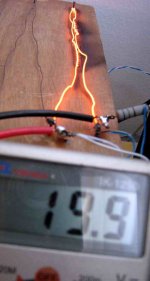
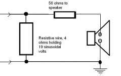
I hate do dissapoint you, but unless your resistive wire is not made for resistors, but is made for heating elements, it's resistance increases with temperature. Also, if you mean 19V RMS then the power into a 3.2 ohm load is 112.8W, not 400... I honestly wish we could lay this Watt thing to rest, you would get 400W approximately into a 1 ohm load... but the amp would not last long.
ilimzn said:your resistive wire .... it's resistance increases with temperature
.
Carlos, I have such resistive wires at home:
One is a thin, with higher resistance/meter.
And the other is of same material, but with lower resistance and thicker = can take more power.
ilimzn,
A question about light bulbs ... lets say normal for mains, 230VAC or whatever AC
I will try to use such bulb, like Nelson in Zenlite, but for another project.
It is not as simple as using my Ohm-meter,
to determine what resistance will be under working condition.
Say I want to use a suitable bulb at 100mA. And like 20 VoltDC or so
across this bulb.
By reading catalogue before ordering such bulb
I want to know of this bulb will be suitable resistance for my amplifier.
In catalogue, I can find these data:
25 Watt for 220VAC
100 Watt for 220VAC
10 Watt for 40V
5 Watt 24V
Is there any way to try to calculate approximate resistance for such, at for example 200mA???
I am quite sure the behavor is same: Resistance will increase with current.
thanks for any helpful info
lineup
( best way is of course practical tests - like Nelson Pass did
But to avoid to order, buy UNSUITABLE bulbs = waste of my money
it would be nice to get some rule of thumb I could use )
- Status
- Not open for further replies.
- Home
- Amplifiers
- Solid State
- Destroyer x Amplifier...Dx amp...my amplifier