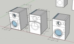
Fellas, these are the drawings of three possible designs. I'm pretty much sticking with the main chamber proportion (already built) but I can play around with the baffle design. Here's what I think about them, from left to right:
1. Double baffle on the midwoofer, supposedly aid with rigidity? The wider circle is how big I will cut out the "main baffle" behind the additional baffle. The chamfer around the edges will supposedly reduce baffle diffraction effects (as shown in exhibit J in the attachment)
2. Again, double baffle on the midwoofer for the rigidity. I'm a bit ashamed to admit I don't know how the baffle shape will affect the tweeter's response. It looks really stout and cool to my eyes 😎😎 Inspired by Troels Gravesen's Discovery-12W
3. Just one layer of baffle, the advantage is simpler construction, and I can put the tweeter closer to the midwoofer to aid better integration of the two drivers.
Across the board, I am planning to measure and then design crossover using XSim accounting for the acoustic center of the drivers.
Any suggestion you guys want to share? As always, I greatly appreciate your kind support. 🙂🙂
Attachments
Last edited:

I'd go for number 1, but with the bevel going all the way around, with a brace ( in red ) between both drivers.
Thanks cracked case, hadn't thought about especially putting the brace between the drivers. Any pointer on how deep it should be? Enough to cover part of the magnet on the mid driver? Thanks again.
I'd imagine a third of the depth of the box would be a good starting point, although I might be tempted to go half way and drill holes through to diffuse internal sound waves.
I think if going with a stepped baffle then number 1 as well. You will likely get some pretty big anomalies in the tweeters response with option 2. I would think you would get them with option 1 as well but less severe (everything is a compromise when building a speaker 😉 ).
Yes to bevel all round as well, but I'd not do it at the bottom. I found out that the hard way 😉 If the speaker is sitting on a surface it will likely cause some nasty diffraction, if it was on a stand (that does not form a V with the bottom of the box) it is probably ok to bevel the bottom.
Tony.
Yes to bevel all round as well, but I'd not do it at the bottom. I found out that the hard way 😉 If the speaker is sitting on a surface it will likely cause some nasty diffraction, if it was on a stand (that does not form a V with the bottom of the box) it is probably ok to bevel the bottom.
Tony.
Fellas, these are the drawings of three possible designs. I'm pretty much sticking with the main chamber proportion (already built) but I can play around with the baffle design. Here's what I think about them, from left to right:
1. Double baffle on the midwoofer, supposedly aid with rigidity? The wider circle is how big I will cut out the "main baffle" behind the additional baffle. The chamfer around the edges will supposedly reduce baffle diffraction effects (as shown in exhibit J in the attachment)
2. Again, double baffle on the midwoofer for the rigidity. I'm a bit ashamed to admit I don't know how the baffle shape will affect the tweeter's response. It looks really stout and cool to my eyes 😎😎 Inspired by Troels Gravesen's Discovery-12W
3. Just one layer of baffle, the advantage is simpler construction, and I can put the tweeter closer to the midwoofer to aid better integration of the two drivers.
Across the board, I am planning to measure and then design crossover using XSim accounting for the acoustic center of the drivers.
Any suggestion you guys want to share? As always, I greatly appreciate your kind support. 🙂🙂
I vote for case #3 because it has fewer steps/edges. Every edge can cause diffraction and effect the speakers off axis response. I would also put generous round overs on the edges and top. The small gain in time alignment from the tweeter step is not worth it IMO.
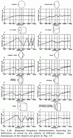
The Olson graphs need some context. Olson used a small special driver in a relatively large baffle to demonstrate the effect. Linkwitz and Dickason also published some graphs with similar (but not as extreme) effects. I second the many suggestions to simulate it one of the many s/w packages mentioned.
Last edited:
@cracked case
@wintermute
@DonVK
Thank you guys, need to care for some non-speakers matter for the time being, I'll check back soon. Have a good one! 🙂
@wintermute
@DonVK
Thank you guys, need to care for some non-speakers matter for the time being, I'll check back soon. Have a good one! 🙂
Hey - little did I know, there’s an opening to sneak out and move forward with the project. 😀😀
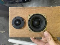
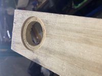
Thank you guys for suggesting to go with flat baffle, I took your advice to heart! 😉
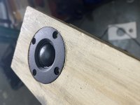
Since I have no access to a router, for this nominally 52mm tweeter, I first made a 3mm ‘score’ with 51mm hole saw, then another 3mm ‘score’ with 44mm hole saw, then drill all the way through with 38mm hole saw. Cleaned up the countersink with a cutter knife. The tweeter sits flush with a tight, press-fit. First time I did this 😱😱 I will line the back of the tweeter with some foam to make airtight and flat fitment.
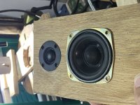
The woofer center is positioned 4/7th of the baffle height. I made sure it’s not in the middle of the cabinet.
Lessons learned: I’m glad I took the time to with the practice jig, and took the time to secure the piece on the drill press when drilling the woofer hole.
Thank you guys for suggesting to go with flat baffle, I took your advice to heart! 😉
Since I have no access to a router, for this nominally 52mm tweeter, I first made a 3mm ‘score’ with 51mm hole saw, then another 3mm ‘score’ with 44mm hole saw, then drill all the way through with 38mm hole saw. Cleaned up the countersink with a cutter knife. The tweeter sits flush with a tight, press-fit. First time I did this 😱😱 I will line the back of the tweeter with some foam to make airtight and flat fitment.
The woofer center is positioned 4/7th of the baffle height. I made sure it’s not in the middle of the cabinet.
Lessons learned: I’m glad I took the time to with the practice jig, and took the time to secure the piece on the drill press when drilling the woofer hole.
Attachments
These were hand calculated and hand drawn, like we used to do back in the day. An admirable pioneering effort and no drivers were harmed during the filming of this episode.The Olson graphs need some context. Olson used a ...
Nice job on the rebating without a router 😱 ! Especially for a first attempt! I like using a router because I'm terrible with trying to do anything precision with hand tools 😉
Tony.
Tony.
You posh people with your routers! - I just use an old broken tap, reshaped to a router bit in a pillar drill.
I am not sure if this qualifies as "designing my own speaker from scratch", but I am trying to take take two different Econowave designs and merge them together.
I am trying to incorporate these speaker designs / crossover designs:
EconoWave SR Compact --> Summary
EconoWave Deluxe --> Summary
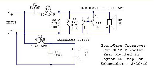
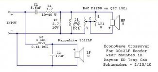
Deluxe uses same compression driver, but different waveguide. Compact SR uses same waveguide, but different compression driver. Deluxe and Compact SR use different woofer, but the Deluxe appears to be closer aligned with the Eminence Beta 12a.
From looking at the FRD on both the DE250 and the Beta 12a, it seems the logical crossover point should be around 1000-1250Hz. The Deluxe crossover seems to crossover at a similar place.
The parts I have ordered are:
Crossover design
I have no idea how to design a crossover, but did some reading on the Introduction to designing crossovers without measurement and from what I have read, the main purpose of the crossover it to cater for the tweeter, or in this case, the Compression Driver. Given the crossover on the Deluxe has been designed for the B&C DE250, I am off to the races (ignoring any effects the waveguide has and taking a "no measurement approach").
The woofer side of things also seems to be similar with both the Kappalite 3012LF and Beta 12a having a hump around 2k, same nominal impedance (8), Re (5 vs. 5.6), Le (0.98 vs. 0.64mH), Sens (95.5 vs 98).
Resistor
I have calculated based on the tutorial a resistor impedance difference of 6.25 (Beta 12a) and 7 (3012LF).
Capacitor
I have calculated based on the tutorial a capacitor difference of 16.38uF (Beta 12a) and 20uF for the (3012LF).
Conclusions
What I can't figure out is why they are using a 12uF cap and 4.5mH resistor and if they are so far off what I was expecting, is my math wrong, and/or are the differences negligible and I can build the crossover as they have spec'd it.
I am trying to incorporate these speaker designs / crossover designs:
EconoWave SR Compact --> Summary
EconoWave Deluxe --> Summary
Deluxe uses same compression driver, but different waveguide. Compact SR uses same waveguide, but different compression driver. Deluxe and Compact SR use different woofer, but the Deluxe appears to be closer aligned with the Eminence Beta 12a.
From looking at the FRD on both the DE250 and the Beta 12a, it seems the logical crossover point should be around 1000-1250Hz. The Deluxe crossover seems to crossover at a similar place.
The parts I have ordered are:
- Eminence B2S-A Aluminum 2/3-Bolt to 1-3/8"-18 TPI Screw-On Horn Adapter
- B&C DE250-8 1" Polyimide Horn Driver 8 Ohm 2/3-Bolt
- Dayton Audio H6512 6-1/2" x 12" Waveguide 1-3/8"- 18 TPI
- Eminence Beta-12A-II 12" Driver
- Waveguide > same as SR Compact
- CD > same as Deluxe
- Driver > neither, but closer to Deluxe
Crossover design
I have no idea how to design a crossover, but did some reading on the Introduction to designing crossovers without measurement and from what I have read, the main purpose of the crossover it to cater for the tweeter, or in this case, the Compression Driver. Given the crossover on the Deluxe has been designed for the B&C DE250, I am off to the races (ignoring any effects the waveguide has and taking a "no measurement approach").
The woofer side of things also seems to be similar with both the Kappalite 3012LF and Beta 12a having a hump around 2k, same nominal impedance (8), Re (5 vs. 5.6), Le (0.98 vs. 0.64mH), Sens (95.5 vs 98).
Resistor
I have calculated based on the tutorial a resistor impedance difference of 6.25 (Beta 12a) and 7 (3012LF).
Capacitor
I have calculated based on the tutorial a capacitor difference of 16.38uF (Beta 12a) and 20uF for the (3012LF).
Conclusions
What I can't figure out is why they are using a 12uF cap and 4.5mH resistor and if they are so far off what I was expecting, is my math wrong, and/or are the differences negligible and I can build the crossover as they have spec'd it.
Attachments
Dear Members,
is it real that until a certain frequency, several woofers/midranges can be used and "logically"/virtually they act as one ?
E.g. I have an idea of packing 4 midranges around a tweeter, can I do it with good results ? (Instead of MTM or classic on-top-of-eachother alignment).
I know we used to stack drivers on top of eachother and avoid placing them next to eachother - when talking about midranges or tweeters at least so that at least we have a point-like source on horizontal plane (while we certainly don't have this on the vertical plane but we're sitting all the time so.. still a good recipe).
I've read something like center to center distance, which means: I can place drivers on-top and next-to eachother freely, as long as their center-to-center distance is within wavelength/2 on a particular frequency. In this region (and below) the drivers act as one and can be modeled (lobe, phase, etc) as one, while above this frequency they start to sound more like individual ones, we loose the coherence. Does it apply, is there such a rule we can rely on ? (e.g. surrounding a tweeter with 4x 3-6" midrange drivers).
It's very possible that four drivers in that arrangement could cause beaming, used on there own cone reduction would reduce this effect but having the centres of the cones in a wide square would negate this. I don't want to put you of this interesting idea ( I had thought of using six woofers around a centre tweeter as a cheaper way to a Tannoy dual concentric ), I think there are advantages to using multiple small light ridged cones instead of one big heavy floppy one.
Okay, so still better to have those midranges rather below the tweeter in a line. (classic way). Thank you.
I'm not saying that for certain, just it would be an idea to experiment first with this arrangement before committing to a full speaker build. Also don't just listen to my opinion, there are others on this site much more knowledgeable than me.
You are correct about it happening.. it sounds as though you have heard it is a bad thing but I would disagree. When beaming is a good thing it may be called directivity control. Ordinarily there is an optimum amount of directivity control for a given system at a given frequency. Often those starting out follow a tried and proven layout to focus on learning other aspects then branch into directivity as they feel more comfortable.
idzy, you ask a big question so I'll try to muddle through it. I've followed Zilch's econowaves a little on the side. I get the impression the crossovers were carefully listened to and tweaked to satisfaction, yet kept simple enough for the builder to work on them.
I'd be happy to be corrected on any of this.
Compression drivers and horns can give exemplary results. The first thing I'd say though are they can be trickier to deal with than domes. For one thing they have a sharper, yet wider impedance peak which is not a problem if you can address it in the crossover. Look at Zilch's cross, there are many parallel components which are serving that purpose.
The next issue is that the horn may have a bumpy response, depending on how it deals with diffraction. Along these lines they also may have a varying directivity which plays into your choice of crossover. I'm kind of hoping Zilch has made that one easier, as I'll describe next.
It's possible that each econowave design that has a given size of woofer also has the same crossover frequency. So (I'm hoping) choosing an econowave variation that uses your model of woofer will show you a woofer crossover that works with other tweeter combinations.
Then choose a tweeter crossover for that same driver and horn, used with a same sized woofer of any model.
Your situation is unique because you want to mix and match a compression tweeter and horn. The interaction here is complex, and to simplify I'd consider trying the crossover designed for the same horn you are using.
It's then important to adjust the level of the tweeter to suit the woofer. As it gets better, change the polarity of the tweeter to see if one sounds right. Get a feel for the crossover frequency band while doing this, as you'll also want to assess the level in this region. Does it sound empty, or is it overpowering. So to begin you match the tweeter level to the woofer, then see that the crossover is blending so that middle part also is at the right level. It could be that the frequencies are too close or far apart, or it could be that they aren't adding well.
Vortex, you might want to check out this thread Nexus - World's Easiest Controlled Directivity Loudspeaker unfortunately for me most of the images are not loading properly, not sure if that is my work proxy or a bigger problem.
Tony.
Tony.
- Home
- Loudspeakers
- Multi-Way
- Design your own speaker from scratch discussion thread