Thank you @AllenB for your thoughtful response! I know I have made a real challenge for myself.
Gainphile has done some work on this specific waveguide and compression driver. His design uses an active crossover though, so he hasn't detailed a specific schematic as such. Essentially what I was trying to achieve is what he has done with the active in a passive model.w
What he has said is:

Gainphile has done some work on this specific waveguide and compression driver. His design uses an active crossover though, so he hasn't detailed a specific schematic as such. Essentially what I was trying to achieve is what he has done with the active in a passive model.w
What he has said is:
Gainphile said:Tweeter DSP crossover
XO: 1250hz, LR2
EQ1: Waveguide loading notch1
PEAK 3981hz / -4.1db / 1.2Q
Raw and eq notch 1 (measured 1m)
EQ2: Waveguide loading notch2
PEAK 1269hz / -3db / 1.5Q
Fully eq'd Tweeter (measured 1m)
Passive L-PAD
Follow the passive -11db LPAD configuration as CD1 above.
Attenuation, Phase, and Delay
With W1: Attenuation -5db, Polarity INVERT, Delay: 0ms (measured 1m)
It looks as though gainphile started with a generic filter type, hit some peaks, pulled down the level and adjusted the phase.
There's not much in that to help here, other than the approximate frequency, and the need to have no less than second order filters to keep the woofer away from breakup. The question is, how do you intend to do yours? Will you set up an L-pad to reduce the level and use a second order filter, or will you try to measure and sim?
There's not much in that to help here, other than the approximate frequency, and the need to have no less than second order filters to keep the woofer away from breakup. The question is, how do you intend to do yours? Will you set up an L-pad to reduce the level and use a second order filter, or will you try to measure and sim?
The schematic has provision for an L-Pad, so I plan on incorporating that. I am hoping that will cater for the differences in driver sensitivity.
Vortex, you might want to check out this thread Nexus - World's Easiest Controlled Directivity Loudspeaker unfortunately for me most of the images are not loading properly, not sure if that is my work proxy or a bigger problem.
Tony.
Hi Tony, wow not bad, thanks. Digesting it. 🙂
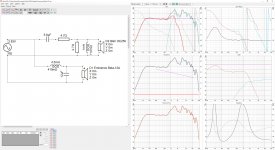
Not sure if this helps any further, but I have managed to get FRD/ZMA data for both and after trying XSim, Engauge Digitizer and VituixCAD, I have come up with the following crossover and graphs.It looks as though gainphile started with a generic filter type, hit some peaks, pulled down the level and adjusted the phase.
There's not much in that to help here, other than the approximate frequency, and the need to have no less than second order filters to keep the woofer away from breakup. The question is, how do you intend to do yours? Will you set up an L-pad to reduce the level and use a second order filter, or will you try to measure and sim?
I don't know if this is the right thread to continue this discussion, but just hoping to get some discussion/help going on the problem I am trying to solve. Hopefully you can see I am motivated to solve.
Attachments
Hi all, I figured out the issue with my crossover network and it is now looking really good! Thank you so much for your support and I will keep up the study and reading. Really keen to buy a UMIK and MiniDSP to start taking some measurements.
Really really appreciate all you guys are doing!
Really really appreciate all you guys are doing!
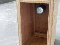
Hello Folks - another progress report. 🙂
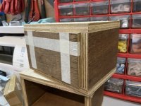
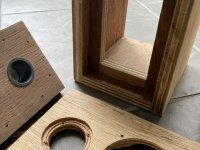
- The baffle has been drilled and chamfered - the difficult part was chamfering with a router without seeing much, I had to go by feel to leave some "meat" around the screwholes.
- Mounting battens and back panels have been trimmed to size - Easy enough but requires a degree of care with the miter saw. Very satisfying when the back panel slides in and holds itself by friction 😉
- I was thinking of using two 22mm ports but I was afraid I'm not gonna have enough space for crossover in the back panel. Another consideration was, the two port holes closely spaced to each other posses a risk of tearout with the material I'm using. I end up with single 26mm port, which according to Unibox limits me to about 90dB SPL before chuffing is introduced.
As always, here's some questions:
- Is it now okay to glue the front to the main enclosure? Or do you guys suggest I do roundover first, or install internal lining first? Then glue it to the main enclosure? This is a 2 liter enclosure, mind you. 😉😉
- Should I fix the port now to the back panel, and consider them as one "unit" when it comes to finishing? I am planning to glue them in place with some epoxy glue, and afterwards do some roundover to create port flare.
Thank you again.
Attachments
Last edited:
Looking good 🙂 It's always a bit tricky deciding when to do the final gluing. I in the past have held off on the final gluing, doing some tests first with the baffles held on with picture frame straps 😉 The one area that could be difficult would be if you decided you needed to tune the port length. It may be better to not glue it in till you are certain the tuning is how you want it.
Closed cell foam tape can be used for a seal when temporarily holding things together for testing 🙂
The main thing is going to be, will you be able to do anything through the main speaker cutout. It's fairly small so will limit access.
Tony.
Closed cell foam tape can be used for a seal when temporarily holding things together for testing 🙂
The main thing is going to be, will you be able to do anything through the main speaker cutout. It's fairly small so will limit access.
Tony.
The main thing is going to be, will you be able to do anything through the main speaker cutout. It's fairly small so will limit access.
Tony.
Thanks Tony, sorry I forgot to mention, I designed this so the back panel is removable 🙂
Is it now safe to glue the front? 😀😀
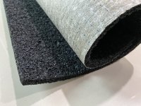
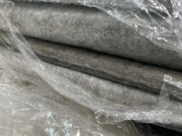
Regarding lining, I have the option to use either the rubbery carpet underlay (as attached) or standard 12mm wool carpet. Any pointer on which one is better? I can also double them up, or maybe in certain spots.
Thanks again for all your kind assistance 🙂
Ah in that case then yes. I routed my front baffles after they were glued on. As I had veneer I veneered right to the edge and then routed.
On the lining, experiment and see how it goes, that's what I did. Just make it tight fitting and sit it in there. I did nearfield measurements to see the effects. They are good for showing reflections through the speaker cone (and how well they have been suppressed).
I did nearfield measurement of bare box, then with different types of linings, some worked much better than others.
Tony.
 looking good
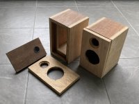
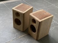
It’s starting to take shape..
Hope you guys are having a good time and staying healthy and safe..
If the backs are removable, perhaps you could fit a diffuser ( just a bit of mdf with holes drilled in and perhaps covered with something like carpet tile, the red stuff in the above picture ) to the back. This can help reduce return reflections from the back panel and possibly stiffen it.
In response to OT discussion here -> First Crossover Design Advice
Kimmo, I originally did not want to publish the thread until it was finished, but after 2 years of answering questions that were addressed by the content I had already written I decided to make the incomplete thread available publicly.
What is there so far the intent is to give people some ideas before they start building. The intention always was to do the sections on doing proper measurements, and simulating crossovers using those measurements.
The tools presented (yours is one of them, and the fact that it has the capabilities that I am talking about indicates that at least at some point you saw value in that) can be used to get an idea of what someone might expect when they pair some particular drivers with a particular cabinet. Not everyone has the luxury (or time) to be able to make multiple prototypes before getting to a point where they can start to make serious progress. The point of what has been written so far is to give the reader a running start.
The yet to be written parts are on doing proper measurements and then to use those measurements to design a crossover. The intention was to actually buy the speakers that the simulations were done on and to build the box that was decided on, and then do the measurements. Comparing actual with what was done as the prep work.
I will eventually do more posts, but life got in the way. I was intending to use vituixcad as the tool to show the design of the crossover, but after problems with my own measurements and sims not matching reality (not something I had had a problem with in the past with other tools) I had to take a step back as something clearly wasn't right, that was back in 2018, and unfortunately I have not been able to revisit since then.
Tony.
Last edited:
There is also the aspect of learning styles (we all have different learning styles) and what phase of discovery a person is in when they come to diyaudio.com and ask a question.
Often times, a person has read and researched the subject on their own, and they are at a point of information overload, or they have come across too much conflicting, or seemingly conflicting, information.
In such cases, this person needs a little nudge in the right direction so they can continue their journey of discovery.
Yes very true! One thing I like to stress is the fact that everything is a compromise, and you have to work out which compromises *you* can live with. Once you start to understand that, the seemingly conflicting info can start to make more sense.
I like to think it is often just different people prioritizing different things. The hard part is working out which things matter to you. 🙂
Tony.
I like to think it is often just different people prioritizing different things. The hard part is working out which things matter to you. 🙂
Tony.
From time to time I like to point out that something could be done better using a more advanced technique, but the results vary.
A person who is increasing their knowledge may simply see it as the next step, but a person at an advanced level is aware of the margin of error in certain techniques. I can understand the potential for the occasional bout of frustration.
Still, that doesn't change the fact that we can go further when taking it at our own pace. The forum environment is good that way, having a blend of saved content and present discussion.
something could be done better using a more advanced technique, but the results vary.
Comprehensive measurement data helps designing crossover so that overall sound balance is close to best possible with selected components and acoustical design (dimensions, shape, ..,). Crossover has crucial role, but it cannot define total quality. Some small sound nuance or total DI or DI tilt of tweeter could be more important than small mistake in sound balancing by crossover. This is self-evident, but my point is that drivers and acoustical design of radiators should support each others and be suitable/compatible with listening environment, acoustics, possible locations of speakers and listener, and preferences of listener. And after that crossover should be designed with full measurement data to verity that good sound balance is achieved without infinite uncontrolled tuning loop and unnecessary costs.
A person who is increasing their knowledge may simply see it as the next step, but a person at an advanced level is aware of the margin of error in certain techniques.
Sure when acoustical concept stays the same and known for the designer. Crossover of traditional speaker is possible to design with axial and few off-axis responses in both planes. All measurements in large space with long time window at listening distance to keep data accurate. Some studies and articles are needed to set sustainable design targets, but after that design work could be routine.
But everything should be started from zero when acoustical design changes without adequate experience with that particular concept. Therefore it's safest and fastest to capture full measurement data and study what is suitable sound balancing for that concept, with controlled manner where basics are okay.
I can understand the potential for the occasional bout of frustration.
Frustration is continuous state of mind for me 🙂
Still, that doesn't change the fact that we can go further when taking it at our own pace. The forum environment is good that way, having a blend of saved content and present discussion.
I think one problem is basic theory. It might be more important than introducing different design tools. We could misinterpret some notions/terms even after multiple e-mails or forum messages. Discussion could turn messy and frustrating without obvious reason. The latest experience:
What are differences between the following and key features related to measurement data for crossover design:
- minimum phase extraction
- minimum phase response
- response (minimum phase or not) with constant delay offset in seconds
- response (minimum phase or not) with constant location offset in meters
- response (minimum phase or not) with variable sound flying time from origin of the radiator to mic/observer, depending on direction in 3D space
- response (minimum phase or not) with variable polarity depending on frequency and direction in 3D space.
- Home
- Loudspeakers
- Multi-Way
- Design your own speaker from scratch discussion thread