I believe this is showing the excursion when tested at each frequency separately and applying 50W to it in each case.
Sure, the response rolls off at the low end but this is ignored which means that you get less out and still lots of excursion. The fixed point being 50W. This means you can't ignore area number 1.
One thing though, this plot also ignores the fact that music doesn't have this even power spread. If there is no recorded energy in area number 1 then you have more excursion to spare.
Vented boxes do let loose below their tuning frequency, however 35Hz isn't too bad. If you did have a problem you could always add a low bass filter.
Thank you a lot for your quick answer. I was actually considering a low bass filter and searched for information on it, if people think this is actually common practice, however it seems not so common to do it.
It would have been much easier to design an enclosure, if I only had to look at area number 2. In my design so far (6mm Xmax), Xmax is only reached with 10V-11V input. When measuring speakers, often 2,83V is used. To me this was almost too loud. That is why I think I would never reach it. However, the design is far from done.
There will be times that you find it helpful to make comparisons with Xmax, but normally I think you should just try it and find out for yourself.
Historically referred to as a 'TT rumble filter'. 😉I was actually considering a low bass filter and searched for information on it

Thanks for the info. What I am looking for are codes for enclosure design, crossover design, frequency response, polar response for on-axis, off-axis in matlab. No physical built of loudspeaker. Just simulation
Hi agree with AllenB response.
For general with hifi (not subwoofers) loudspeakers you don’t need to stress too much about Xmax limitations as a determining factor in your design.
Most consumer hifi loudspeakers are not designed to deliver their rated maximum spl at the loudspeaker’s F3 because in practice it’s not going to happen.
If you are interested in maximum spl at frequencies below 100 hertz use a simulator like Speaker Box Lite which is a smart phone App.
In more detail the Xmax of a driver is a measurement of the drivers linear excursion within the voice coil gap where the BL curve is maintained to a given amount as a %. Ie 10%. The driver can usually exceed the Xmax up to the peak physical Xmax before damaging the suspension components.
The fundamental difference in a small versus large woofer is the difference in the peak cone excursion required for a given acoustic output. Doubling the cone area results in 1/4 of the required peak excursion for example at 50 hertz. This typically results in lower distortion and improved LF linearity. A larger woofer in a larger enclosure will normally sound bigger than a smaller driver in a smaller enclosure. It’s just how it works. There are exceptions like Carvers cube sub which requires 2700 watts of amplifier power to produce the same output at an 18 inch subwoofer. But that’s not a hifi loudspeaker application.
There are tricks a designer can use to improve the low frequency output of for example a tower loudspeaker. Multiple smaller 6 1/2 woofers with progressive high pass filters passive crossovers points increase low frequency output.
Secondly, DSP in an active loudspeaker can be used to tune the woofer to an assisted bass reflex alignment- B5 or B6 which enables the woofer to operate at a lower port tuning frequency with an electrically boosted and equalised response with high pass filter to protect the woofer. Small active studio monitors typically use the approach for enhanced low frequency output.
Recent advances in small driver magnetic systems and suspension systems have improved the maximum low frequency output. The Purifi loudspeakers are an example of innovative design and are set to change the landscape of smaller high performance loudspeaker drivers.
One further point is that with careful intuitive design the low frequency response of loudspeaker enclosure as a system can be set up to benefit from room boundary reinforcement where the junction of a wall and floor offer up to 6db in effective output level below 100 hertz.
Typically a loudspeaker with a maximally flat response to 40 hertz would result in a hump in the low frequency range when move close to a wall / floor boundary junction.
The designer can customise the woofer/ enclosure tuning to provide a smooth low frequency output which can extend to a 35 - 40 hertz F3 when the enclosure is in proximity of the wall / floor boundary junction. This is now common in modern consumer loudspeakers.
The upshot of this is that the diy loudspeaker builder may find his enclosure simulations don’t agree with consumer designs.
The approach taken in consumer designs starts with selecting a woofer, enclosure footprint and a simulation. Prototypes are then tested in a number of real consumer listening environments and are modified and tuned until the design goal is met. Attempting this with a full passive system involves a degree of skill and design complexity.
For example the designer might need to account for baffle step diffraction and in room boundary effects to obtain an satisfactory low frequency balance. Achieving this normally requires assembly and testing of several prototype systems.
Typically a diy loudspeaker builder will seek to finalise his loudspeaker design at simulation stage and then build the design without testing or modifying the low frequency aspect of the system
The diy loudspeaker builder can use dsp equalisation such as Dirac to simplify obtaining a smooth in room low frequency response.
The point of my posts here is to offer an awareness to the diy loudspeaker builder of the wider holistic approach taken in commercial consumer hifi loudspeakers.
I would encourage diy loudspeaker builders to think outside the box if they have specific expectations. For example Roy Alison’s patent clearly outlines an approach to obtaining a relatively smooth low frequency response in a consumer environment.
The principles are not difficult to grasp.
Because the diy loudspeaker builder is not constrained by factory production costs or marketing challenges he can explore techniques such as the Alison Dip. Such design principles are featured in high end designs by Estelon Loudspeakers.
The principles are not difficult to grasp.
Because the diy loudspeaker builder is not constrained by factory production costs or marketing challenges he can explore techniques such as the Alison Dip. Such design principles are featured in high end designs by Estelon Loudspeakers.
This is a great resource, thanks for putting it together!
One tool I use for makng round holes neatly and consistently is a hole cutting jig. I use a Jasper Jig but there are many kinds out there sold by woodworking supply stores, and if you have the time and skill you can make your own easily from hard board. I use a spiral up-cut bit to get a smooth cut, and a dust collection hood connected to my shop vac to catch the MDF dust.
Some folks use a saber saw and sanding drums on a drill for this but once you router a nice clean hole you will throw the saw in the trash.
Most of my routing these days is done with a trim router. It’s got 1 1/2 horsepower, more than my old full sized router, and it’s lighter. I still use the old router to cut round overs because it has a 1/2 inch collet.
Regarding your aversion to solid wood, I somewhat disagree. First look at all the fine furniture that exists in museums that is hundreds of years old, the vast majority of it is not split or cracking. I have antique furniture that has gone from South Carolina to Colorado and not split. I have a solid cherry bedroom suit that has traveled around the world with me that has no cracks or warps in it. Wood as a material can be very uniform and stable.
Granted it takes a somewhat experienced carpenter to know good sources for kiln dried lumber, to know the characteristics of the wood, how to test for consistency, and understand how the wood changes with humidity. Stick with one species from the same lot of lumber and you should be OK.
I see no problem with an amateur making small enclosures out of solid wood. Large floor standing speaker systems however can be troublesome if not constructed properly. Also, making speakers from up-cycled pallets is simply looking for trouble.
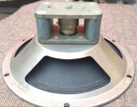
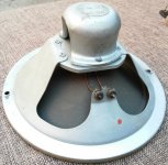
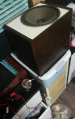
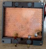
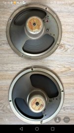
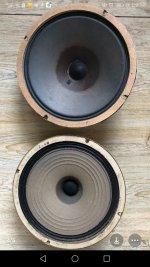
I don't design my speakers. I design the experimentation that would yield the results I wanted, empirically and efficiently. Yesterday morning I took delivery of two different 8" vintage fullrange drivers (old German, were they a pair would more than double the cost). After a quick listen (tone-sweep and reference music) I planned out what to try over a two-hour window in the evening. The 1930s Telefunken sounded fine and flat-responsed except it had resonance around 90hz; it was placed over a steel umbrella stand (21cm diameter tube 50cm high ~17L overstuffed and slightly leaky). The (later) Siemens had a very big hump 2-4.1khz and associated distortion. Without measuring impedance curve, I simply tried two each L C R in combination and notched out the hump while balancing the two drivers; it went on a 14L aperiodic box stuffed with a woolen jacket. That left only ~110hz ('funken) vs ~320hz ('mens) tone-sweep minor humps to be dealt with later. Crystal clear neutral "German" sound, 75-10500hz very well covered, the Funkmens!
(Actual cabs will take another round of experimentation, aperiodic vs TLonken etc.)
(Actual cabs will take another round of experimentation, aperiodic vs TLonken etc.)
Attachments

Last edited:
Good question actually, neither driver explicitly labelled. The rectangular magnet structure older driver was represented as Telefunken, the other as Siemens, by an Idlefish Market seller (i.e. bulk importer) of old German speakers and tubes etc. Soundclips were promising and price was right, I guess 🙂Who’s German drivers?
Attachments
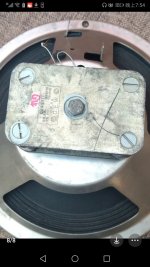
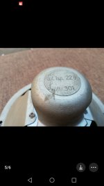
The 1930s "Funk" is quite unusual looking; the Siemens shape is pretty commonplace (on Idlefish Market anyway) except for different magnets.
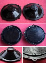
But... encouraged by the old Germans I quickly snatched two 8" Celestion taken from one vintage radio console -- 15ohm mid-woofer and 5ohm mid-tweeter so to speak. If midrange covered 80-8k. Long story short -- I made them close-enough sounding by levelling-off the mid-tweeter's HF using (1.5mH||9ohm||2.7-3.3uF? yet-to-be-finalized), in 14L aperiodic. Now each sounded basically flat 75-9000, extending to 60-11000. I really like vintage Celestion's mellifluous, faintly-glowing sound, but they are rather hard to find and somewhat expensive. So I finally have a "pair of eights" for $90.
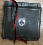
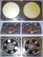
An electrostatic supertweeter (labelled Grundig) was part of the set, but at normal max voltage was way too faint to be heard especially above 9khz. Ideas anyone?
Interestingly, the two eights played straight-through wired in parallel sang gorgeously together -- as originally designed. Like my "stacked pairs" of complementary speakers (stereo bipoles).
But... encouraged by the old Germans I quickly snatched two 8" Celestion taken from one vintage radio console -- 15ohm mid-woofer and 5ohm mid-tweeter so to speak. If midrange covered 80-8k. Long story short -- I made them close-enough sounding by levelling-off the mid-tweeter's HF using (1.5mH||9ohm||2.7-3.3uF? yet-to-be-finalized), in 14L aperiodic. Now each sounded basically flat 75-9000, extending to 60-11000. I really like vintage Celestion's mellifluous, faintly-glowing sound, but they are rather hard to find and somewhat expensive. So I finally have a "pair of eights" for $90.
An electrostatic supertweeter (labelled Grundig) was part of the set, but at normal max voltage was way too faint to be heard especially above 9khz. Ideas anyone?
Interestingly, the two eights played straight-through wired in parallel sang gorgeously together -- as originally designed. Like my "stacked pairs" of complementary speakers (stereo bipoles).
Attachments
-
 IMG_20230115_192332.jpg343.1 KB · Views: 117
 -
 Screenshot_20230115_192617.jpg337.5 KB · Views: 109
 -
 Screenshot_20230115_192523.jpg298.7 KB · Views: 110
 -
 Screenshot_20230113_211743_com.taobao.idlefish.jpg311.8 KB · Views: 121
 -
 Screenshot_20230113_211831_com.taobao.idlefish.jpg308.3 KB · Views: 111
 -
 Screenshot_20230115_203626.jpg303.5 KB · Views: 116
Last edited by a moderator:
The Grundigs are an example of the very common use of single ended ESL tweeters driven directly by the output stage bypassing the OPT. The bias also comes from there.
There is a whole thread on them i believe, i know i have posted. alot of pictures and some information at least a couple times.
dave
There is a whole thread on them i believe, i know i have posted. alot of pictures and some information at least a couple times.
dave
Much thanks. I could only find 2006 and 2021 mentions, a "used FR drivers second life" thread for cones (ID by fuzzy picture wow), and a couple of occasional pics and circuits, one pic matching the Grundig. With only two wires red & black coming out of the ESL twitter unit, I'm still at a loss how to supply plate & bias high voltage from my EL84 (if and when I decided to try it for the experience).
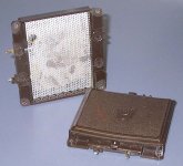
The radio console from which it came did have a junction plate with two small-size resistors (the seller forgot to send) either for the ESL HV or for balancing the cones. He's going to try to get another console from the UK....
The radio console from which it came did have a junction plate with two small-size resistors (the seller forgot to send) either for the ESL HV or for balancing the cones. He's going to try to get another console from the UK....
- Home
- Loudspeakers
- Multi-Way
- Design your own speaker from scratch discussion thread