Hi Shaan,
How to adjust the gain of DOZ ?
thanks
kp93300
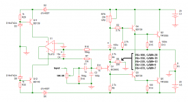
See the attachment, it shows how you can connect the 10K(or 100K) volume pot to the DOZ and a table where you can determine the gain of the circuit with varying value of R6. Remember, a gain more than 28 or less than 7 may either introduce high distortion due to low feedback factor or damage the circuit due to oscillation, and should not be implemented without the assistance of an oscilloscope.
Hope this helps.
p.s. The default gain is 13.
Attachments
Last edited:
Pd = Pmax * [Tmax - Tc] / [Tmax - T25]
using Pmax = 120W
Tmax = 150°C
Tc = Ts + 15Cdegrees = 70+15 = 85°C
The maximum power of the 3055 with a 70°C heatsink interface temperature is de-rated to ~ 120 ~ 65 / 125 = 62W.
Running the hottest part of the heatsink @ ~70°C effectively reduces your 3055 to a 62W device. Then you must de-rate for second breakdown at all the higher Vce imposed on the 3055.
Some 3055 have a Pmax of 90W @ Tc=25C.
HI AndrewT,
I read from ESP that the power dissipation per device for DOZ is 38W. This is below 62 W as stated above.
Am i correct in the interpretation.?
Is there any risk of damage to the speaker if one of TIP 3055 is blown while in use ?
thanks
kp93300
Now use the 62W and the second breakdown limits to investigate the SOAR of the device while passing a quiescent 38W and simultaneously a sinewave signal into a complex reactance.
Parallel TIP 3055 to increase power dissipation.
Hi Shaan
From the feedback, I think there a problem of power dissipation for the TIP 3055.
See the attached picture.
Is this a correct way to parallel the TIP 3055?
Or
can i just wire the additional TIP 3055 in parallel with the existing base, collector and emitter pins of the TIP 3055 ?
thanks
kp93300
Attachments
No.
you cannot wire in parallel BJTs where some are without emitter resistors.
You need to modify the circuit to insert the emitter resistors. Optimise the new circuit to get it working properly and then you can parallel the output devices.
you cannot wire in parallel BJTs where some are without emitter resistors.
You need to modify the circuit to insert the emitter resistors. Optimise the new circuit to get it working properly and then you can parallel the output devices.
Is there any risk of damage to the speaker if one of TIP 3055 is blown while in use ?
thanks
kp93300
The speaker is always in danger when power transistors blow in a Direct Coupled amplifier. This is the true for all sillicon based BJTs. Use fuse or other kinds of protection if your speakers are precious/expensive. In my experience I have blown many transistors due to overload/overheating, but the speaker was never damaged.
Now use the 62W and the second breakdown limits to investigate the SOAR of the device while passing a quiescent 38W and simultaneously a sinewave signal into a complex reactance.
I think KP has already declared himself as not "so much" expert about electronics, etc. We need to give him a lot more time for that, IMHO.
Hi Shaan
From the feedback, I think there a problem of power dissipation for the TIP 3055.
No, as long as you are keeping the TIP3055s cool in every way you can. Use a bigger heatsink if possible. Or maybe a 12VDC fan run at 6VDC.
See the attached picture.
Is this a correct way to parallel the TIP 3055?
Or
can i just wire the additional TIP 3055 in parallel with the existing base, collector and emitter pins of the TIP 3055 ?
thanks
kp93300
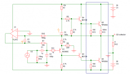
See the attachment, this is how you can connect two 3055s in parallel. You do not need to modify Anything in the circuit board. Connect one 0.1ohm resistor to each emitter of every 3055s and join the bases and collectors as shown inside the black rectangles. You can do all the wiring on the 3055s mounted on the heatsink.
All the best.
Attachments
Last edited:
Hi guys,
I'm rekindling my interest in Class A amplifiers and this DOZ project with offset servo and a nice PCB layout courtesy of Shaan makes me want to do this again. 5 years ago, I tried the single supply JLH powered by an open frame 27V 7A supply. It sounded nice although I worried that the loud thumping sound when you turn it on might eventually damage the speakers over time. So to the basement it went.
I would love to implement the DC coupled DOZ. I do have a few questions so would really appreciate your comments and suggestions.
1. I already have two fix 27V/7A power supplies so that takes care of the split supply. Will the values of the components, specially the resistors have to be adjusted since the current supplies are at +/-20V?
2. What causes the power on thump/pop sound on the speakers?
3. In our country, finding the component Zener diode might be more difficult than say a fix regulator. If I use a 7812/7912 or LM317/337 regulators for the op-amp, does this have any effect/s on sound quality?
Thanks in advance.
Hi guys,
I'm rekindling my interest in Class A amplifiers and this DOZ project with offset servo and a nice PCB layout courtesy of Shaan makes me want to do this again. 5 years ago, I tried the single supply JLH powered by an open frame 27V 7A supply. It sounded nice although I worried that the loud thumping sound when you turn it on might eventually damage the speakers over time. So to the basement it went.
I would love to implement the DC coupled DOZ. I do have a few questions so would really appreciate your comments and suggestions.
1. I already have two fix 27V/7A power supplies so that takes care of the split supply. Will the values of the components, specially the resistors have to be adjusted since the current supplies are at +/-20V?
2. What causes the power on thump/pop sound on the speakers?
3. In our country, finding the component Zener diode might be more difficult than say a fix regulator. If I use a 7812/7912 or LM317/337 regulators for the op-amp, does this have any effect/s on sound quality?
Thanks in advance.
Ans 1:
If your power supply is +27V(single supply) then nothing needs to be changed, but you cann't use the direct coupled version. If it's +-27V(dual supply) supplies then you can use the direct coupled version and only the input BJT and the 20K VR need to be changed because BC559/560 has too low VCE and 20K would make too much current to flow.
2SA970BL is a great replacement fot the BJT and you may need 50K or higher value for the VR.
Ans 2:
In a direct coupled amplifier the thump is caused by assymetric turn-on of the upper and lower part of the circuit. As the output rail needs a little time to settle at near 0V, one of the power transistors turn on before the other or conduct more than the other and the difference voltage is presented to the speaker. This can be totally eliminated using modern design practices and is fairly easy.
In a capacitor coupled amplifier it can be caused by the same reason as above, plus the charging of the feedback and output capacitor. This charging is inevitable and people often use time-delayed relay systems to protect their drivers.
In the direct coupled DOZ both caps were eliminated, and the servo was designed to turn on as fast as possible; as a result, no thump.
Ans 3:
You can use the regulator ICs for the opamp without any problem. This has no effect on the sound quality.
Last edited:
Hello Shaan,
Appreciate your answers. Do you have like a bill of materials needed for this project? There's not many but I'm concerned with the voltage ratings of the capacitors and power ratings of the resistors.
I've checked the 2SA970BL here but it's not available locally. I still have a few of the BC560C and my question is, what is the risk of exceeding the VCEO of 45V?
I've read the whole threads/post and wouldn't deviate further from the other members' build experience. Nice looking with plenty of DIY touch. Can't wait...
Regards.
Hello Shaan,
Appreciate your answers. Do you have like a bill of materials needed for this project? There's not many but I'm concerned with the voltage ratings of the capacitors and power ratings of the resistors.
I don't have a bill of material ready yet. The capacitors should be rated at minimum of 40V and all resistors should be 1/4 watt or 1/2 watt metal film type except the 0.1ohm; this should be a 2 watt metal film or wirewound type.
I've checked the 2SA970BL here but it's not available locally. I still have a few of the BC560C and my question is, what is the risk of exceeding the VCEO of 45V?
The risk is that the BJT will work unpredictably and will probably fail; the datasheets supply device parameters from tests done well below VCEOmax.
I've read the whole threads/post and wouldn't deviate further from the other members' build experience. Nice looking with plenty of DIY touch. Can't wait...
Regards.
No need to wait. Start ASAP. All the best from all of us.

Cheers 😎
2SA970 are easilly available.
These guys will help anywhere in the World.
Cricklewood Electronics - CCTV. CCTV Equipment. CCTV Systems. Digital CCTV Cameras
and these
http://www.dalbani.com/CGI-BIN/LANSAWEB?WEBEVENT+L1643823473882200D48000E+M36+ENG
These guys will help anywhere in the World.
Cricklewood Electronics - CCTV. CCTV Equipment. CCTV Systems. Digital CCTV Cameras
and these
http://www.dalbani.com/CGI-BIN/LANSAWEB?WEBEVENT+L1643823473882200D48000E+M36+ENG
wponline,
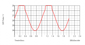
You can use a BC560C (45V VCEO) transistor as the input BJT in a +-27V circuit, as the voltage around the BJT will hardly cross +30V even during clipping. Well within safe zone. See the differential voltage during clip(PS at +-27V) waveform in the attachment.
You can use a BC560C (45V VCEO) transistor as the input BJT in a +-27V circuit, as the voltage around the BJT will hardly cross +30V even during clipping. Well within safe zone. See the differential voltage during clip(PS at +-27V) waveform in the attachment.
Attachments
Last edited:
A couple more volts than one supply rail.
560 could be used at up to +-40Vdc.
556 <=+-55Vdc.
You can add diodes across the bases of the LTP and/or Zeners from signal to return for further protection.
560 could be used at up to +-40Vdc.
556 <=+-55Vdc.
You can add diodes across the bases of the LTP and/or Zeners from signal to return for further protection.
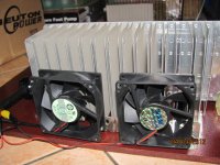
twin fan
I followed Shaanś suggestion about fan to increase efficiency of the heatsink and read up the article in ESP.
I tried different size fan operated at different V. This is my implementation and after about 1/2 hr, the temp at the TIP 3055 is about 55 deg c with a bias of 1.75 amp.
The fan are retrieved from old pc power supply and run at 6 V in the implementation..
I hope this is the final hurdle to enjoying DOZ 😀
regards and thanks to all .
kp93300
Attachments
I followed Shaanś suggestion about fan to increase efficiency of the heatsink and read up the article in ESP.
I tried different size fan operated at different V. This is my implementation and after about 1/2 hr, the temp at the TIP 3055 is about 55 deg c with a bias of 1.75 amp.
The fan are retrieved from old pc power supply and run at 6 V in the implementation..
Just one last small thing... turn the fans so that they push air towards the heatsink. This will cool the heatsinks much more efficiently and will also prevent dust buildup during long term operation.
I hope this is the final hurdle to enjoying DOZ 😀
regards and thanks to all .
kp93300
You are welcome. Enjoy your music with DOZ.
CHEERS!🙂
HI
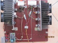
I made a little more progress by installing a speaker protection module and a LM 317 reg for the 4 fans and is listening to it now via test speaker.
There is negligible hum despite the poor wiring. It has the sound characteristics of JLH 69 . Very promising and will do a formal comparison later when it is moved to my main step up.
I noted 2 minor problems :
1) I notice that it is very sensitive to switches of power supply in other parts of the house. There is a rather obvious thump audible through the speaker.
2)The bias current fluctuates between 1.5 amp to 1.8 amp.Input V is 22 V to 23 V
Hi, Shaan is there anyway of stabilising these?
I post a photo but excuse me for the very basic build. I have turn the fan to blow air towards the heatsink and temp at the output transistor is less than 55 deg C.
thanks to all for the guidance
I am very happy as this is my first successful amp build point to point and is probably cheapest amp to build.!
kp93300
Attachments
1) I notice that it is very sensitive to switches of power supply in other parts of the house. There is a rather obvious thump audible through the speaker.
2)The bias current fluctuates between 1.5 amp to 1.8 amp.
ad 1) wiring, shielding, grounding (of all audio chain components). Do you have an input RC filter
ad 2) if it fluctuates up and down and back, most likely you might experience high frequency oscillations. Check with an oscilloscope.
Hi Pavel,
Thanks for your pointer .
I will do a better power supply . The capacitance in the power line may be too low as suggested..
I do not have a scope but the bias current is quite stable after 1/2 hr
The fluctuation changes between different start up , even allowing for stable temp after about 15 minutes. The temp on the tip 3055 is very stable usually about 52 C deg
regards
kp93300
Hi 93300,
as input RC filter, I meant the filter at the signal input, something like 1 kohm + 330pF. It prevents HFI and RFI frequencies to dynamically overload input and also prevents rectification on p-n junction of the input bipolar transistor.
Regards,
as input RC filter, I meant the filter at the signal input, something like 1 kohm + 330pF. It prevents HFI and RFI frequencies to dynamically overload input and also prevents rectification on p-n junction of the input bipolar transistor.
Regards,
Sound impressions of DOZ - Shaan version compared to JLH 69.
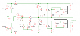
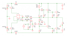
I follow the schematic posted by Shaan earlier in the thread and there is a 1K in series with the base of BC 557B and a 100p cap to ground
I investigate further and noted that it may be related to the fluctuating power V that varies from +/- 22 to 23.5 V.
The article in Rod site use zener to stabilized the Iq. Can this be done here?
PMA , I have attached the schematic that i use below.
Hi all
I hook up to my main speaker for the first time just now and is amazed by the sound.
It is certainly more transparent than the JLH69 I was using prior to the changeover. .
i am pleasantly surprised by this as the build is rat nest wiring and use very ordinary parts . the power filter is only 60 K uf for 2 channels.
I certainly suggest that those who like JLH type of sound should have a go at this .
I will provide more impressions when I have more experience.
regards
kp9300
Hi PMA,Hi 93300,
as input RC filter, I meant the filter at the signal input, something like 1 kohm + 330pF. It prevents HFI and RFI frequencies to dynamically overload input and also prevents rectification on p-n junction of the input bipolar transistor.
Regards,
I follow the schematic posted by Shaan earlier in the thread and there is a 1K in series with the base of BC 557B and a 100p cap to ground
I investigate further and noted that it may be related to the fluctuating power V that varies from +/- 22 to 23.5 V.
The article in Rod site use zener to stabilized the Iq. Can this be done here?
PMA , I have attached the schematic that i use below.
Hi all
I hook up to my main speaker for the first time just now and is amazed by the sound.
It is certainly more transparent than the JLH69 I was using prior to the changeover. .
i am pleasantly surprised by this as the build is rat nest wiring and use very ordinary parts . the power filter is only 60 K uf for 2 channels.
I certainly suggest that those who like JLH type of sound should have a go at this .
I will provide more impressions when I have more experience.
regards
kp9300
Attachments
- Home
- Amplifiers
- Solid State
- Death of Zen 15 watt Power Amplifier