Appreciate your detailed input, Shaan. I have read the articles of Rod Elliot with much interest. His webpage is an invaluable source of information, indeed.
Thanks once again.
Reji
Thanks once again.
Reji
Inverted output?
Hi all.
Could anyone tell me if the output of the DOZ is inverted? Like should the speaker + go to the output capacitor or, if inverted, the - ?
I have had the circuit up and running but I am in the middle of putting it all in the case and need to know where to position my capacitors. I am pleased with the sound, especially the bass! It should sound nicer once finished rather than being connected together by 15 crocodile leads 🙂
Some progress pics..


Cheers, John.
Hi all.
Could anyone tell me if the output of the DOZ is inverted? Like should the speaker + go to the output capacitor or, if inverted, the - ?
I have had the circuit up and running but I am in the middle of putting it all in the case and need to know where to position my capacitors. I am pleased with the sound, especially the bass! It should sound nicer once finished rather than being connected together by 15 crocodile leads 🙂
Some progress pics..
Cheers, John.
Last edited:
Hi all.
Could anyone tell me if the output of the DOZ is inverted? Like should the speaker + go to the output capacitor or, if inverted, the - ?
I have had the circuit up and running but I am in the middle of putting it all in the case and need to know where to position my capacitors. I am pleased with the sound, especially the bass! It should sound nicer once finished rather than being connected together by 15 crocodile leads 🙂
Some progress pics..
View attachment 272381View attachment 272382
Cheers, John.
The boards look cool John. Congratulations!

DOZ's output is non-inverting, so the speaker + goes to output capacitor.
Once again, that chssis leaves me drooling... !
How are the midrange and highs coming? Also, what are you using as the input transistor?
Last edited:
Hi Shaan or others
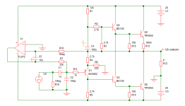
Please confirm the cap orientation in the schematic below
thanks
kp93300
C4 polarity is right. C5 polarity needs to be inverted. Correct schematic shown below.
Attachments
Sha,
follow the circuit from junction of C4&R4, thro' R4 thro' Q1 eb, thro' R11, thro' R7, past C5, to X1 out PIN.
For current to flow from amp Output to opamp Output then the opamp Output must be negative relative to amp Output.
That requires the polarised cap C5 to be returned to the position it is in, in post44.
Kp,
Does C5 need to be that big?
Would a film cap ~1uF do the job?
Last edited:
Kp,
Does C5 need to be that big?
Would a film cap ~1uF do the job?[/QUOTE]
HI Andrew,
I do not know about the value of C5 caps. I am an illiterate in this aspect and I am following Shaan circuit
thanks for the pointer. I will try your suggestion later
regards
kp93300
Does C5 need to be that big?
Would a film cap ~1uF do the job?[/QUOTE]
HI Andrew,
I do not know about the value of C5 caps. I am an illiterate in this aspect and I am following Shaan circuit
thanks for the pointer. I will try your suggestion later
regards
kp93300
The boards look cool John. Congratulations!
DOZ's output is non-inverting, so the speaker + goes to output capacitor.
Once again, that chssis leaves me drooling... !
How are the midrange and highs coming? Also, what are you using as the input transistor?
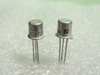
Hi Shaan. The input transistor is a BC179C - same as BC559 but a TO-18 metal can type. I prefer the look of them 🙂
Yes, it sounded nice, which is why I built the second board. It's almost complete, so i'll post an update soon. Cheers!
Sha,
follow the circuit from junction of C4&R4, thro' R4 thro' Q1 eb, thro' R11, thro' R7, past C5, to X1 out PIN.
For current to flow from amp Output to opamp Output then the opamp Output must be negative relative to amp Output.
That requires the polarised cap C5 to be returned to the position it is in, in post44.
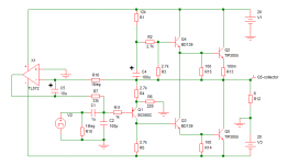
See the attachment, notice the voltage markers. In order to maintain 0V at the output the opamp must pull the input bjt base voltage lower than 0V. This is possible only if the opamp presents a negative voltage through the 33K resistor. As the voltage at the inverting input of the opamp is much positive than its output so the cap should have the +ve pin connected to the inverting input.
Attachments
Kp,
Does C5 need to be that big?
Would a film cap ~1uF do the job?
HI Andrew,
I do not know about the value of C5 caps. I am an illiterate in this aspect and I am following Shaan circuit
thanks for the pointer. I will try your suggestion later
regards
kp93300
KP, the cap's purpose is to form a (very) low-pass filter with the opamp. But the lowpass circuit also has the abilty to provide gain in the very low frequencies at which it works. The 33K resistor also has effect on this and this resistor's value also needs to be decreased if you decrease the value of C5 in order to avoid unusable and potentially dangerous voltage gain at the very low frequencies. I used a 4.7uF film capacitor for C5 with 33K for R7. You can of course use a 1uF film cap for C5 but then will need 15K for R7, in order to maintain the same low frequency response. This, however, will also decrease the amp's input impedance less than 15K, but I think an input impedance above 10K will be fine for almost any source material.
So here is the simple picture:
With 10uF C5, use 33K R7.
With 1uF C5, use 15K R7.
Hi Shaan. The input transistor is a BC179C - same as BC559 but a TO-18 metal can type. I prefer the look of them 🙂
Yes, it sounded nice, which is why I built the second board. It's almost complete, so i'll post an update soon. Cheers!
Cheers! I'm waiting! ALL THE BEST!
Last edited:
HI Shaan
I follow the schematic in post 49 and one channel is ready to hook up to power supply soon.
How to adjust VR2 , the 20K Vr ?
thanks
kp93300
I follow the schematic in post 49 and one channel is ready to hook up to power supply soon.
How to adjust VR2 , the 20K Vr ?
thanks
kp93300
HI Shaan
I follow the schematic in post 49 and one channel is ready to hook up to power supply soon.
How to adjust VR2 , the 20K Vr ?
thanks
kp93300
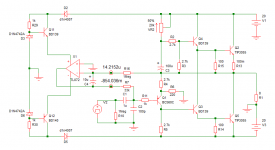
VR2 setting:- Turn VR2 to its maximum resistance, connect the power supply, note the quiescent current, turn VR2 slowly to decrease its resistance while keeping track of the bias, stop turning when bias reaches 1.4A. After a couple of minutes the bias will increaese automatically to about 1.7A as the transistors heat up and stabilize. If the bias climbs more than 2A after a while, then decrease it with turning the VR2 to the opposite direction(more resistance).
For tracking the current you can place a 1ohm/5watt resistor in series with the + supply and probe the voltage between its pins in case you don't have other arrangements; 1V measured around the 1ohm resistor means 1A of current flowing through the circuit.
All the best!
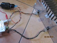
Hi
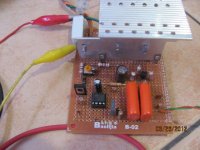
My build is not as neat as Shaan but i am happy ! It is alive !
I tested one channel with V in of +/- 22.8 V . This are ordinary parts from the local store.
There is no switch on or off thumb and the dc offset is 0 V .There is good clarity through the test speaker.
However, I cannot bring the bias to below 1.8 amp despite the full resistance of 20 K at VR2.
It climb to about 2.1 amp and the temp at the holding screw for tip 3055 is about 68 deg c.
I think i have to increase the value of VR2 to 30 K and try.
thanks to Shaan.
kp93300
Attachments
Last edited:
Hi
My build is not as neat as Shaan but i am happy ! It is alive !
I tested one channel with V in of +/- 22.8 V . This are ordinary parts from the local store.
There is no switch on or off thumb and the dc offset is 0 V .There is good clarity through the test speaker.
Great! I am very happy to hear this! Your build looks very compact. Congratulation!
However, I cannot bring the bias to below 1.8 amp despite the full resistance of 20 K at VR2.
It climb to about 2.1 amp and the temp at the holding screw for tip 3055 is about 68 deg c.
I think i have to increase the value of VR2 to 30 K and try.
thanks to Shaan.
kp93300
Just add a 10Kohm resistor in series with VR2 and the problem will be gone. One end of the resistor goes to +ve supply and another end to VR2. I am doing this too. Sorry I forgot to put it in the schematic as the schematic was for simulation purpose only.
The 30K pot will always have less precision than 20K one. So this mod will solve the problem and setting the current will not become hard. Initially I planned to put a 100K pot there but they have too low precision and just a little pressing with a finger over the pot changed the bias to +-500mA!... Followed some experiments and I concluded with 10Kohm+20K VR2.
Cheers!
I just bought 4 of BC177 TO18 bjts out of curiousity after reading m0ukd's posts. I'll install them in the DC coupled board in place of the BC559. Wonder how they are gonnna make DOZ sound.
Attachments
Last edited:
I just bought them because I like the look of metal can transistors 😉
I have pretty much finished my DoZ. I had to install the Q3 emitter resistors to help with stabilization as my heatsinks are not huge, seems to be working well at the moment. I'll leave it on all day tomorrow and see! I used 0.22Ω 5w resistors as I have a few laying about. I think that might be the last part of construction 🙂
Sounds great!
M0UKD, I have been using only plastic transistors for the last three years and these metal can small transistors look cute and sexy! LOL...
Nice to hear your DOZ progress. Ya let it burn for a day or two, I have done so many times with music playing non-stop all day all night and without any bad report, good test for long term stability. Glad to know that you like its sound too.
I love your signature; it's so true!
Nice to hear your DOZ progress. Ya let it burn for a day or two, I have done so many times with music playing non-stop all day all night and without any bad report, good test for long term stability. Glad to know that you like its sound too.
I love your signature; it's so true!
Last edited:
HI
I fire up the other channel last night but the bias start from about 1.5 amp and climb rapidly. The tip 3055 is dead within 30sec !
I will do troubleshooting tonight. Any pointers would be much appreciated.
VR2 is 20 K +10 K
Any need for matching the hfe of the TIP 3055?
Is there any likelihood of BD 139 damage?
Is the quality and quantity of C3 critical in sound quality?
MOUKD any more input about the sound of your DOZ?
thanks
kp93300
- Home
- Amplifiers
- Solid State
- Death of Zen 15 watt Power Amplifier