So we expect some distortion from them.
It doesn't seem to be quite so simple. Especially with such low resistors values.
Selfy, please double check your sims, as mine shows the opposite: much lower distortion with the diodes in place.
My faith in the sim is limited as my physical amps generally seem to distort less than what the sim predicts.
Now i have little choice but to actually measure the distortion without the diodes 🙁
Attachments
It could be that there is some limitation coming from the CCS together with the diode/absence of diode. Without diode the output impedance seems to be higher so higher is the distortion.
To drill a bit you should try, if possible, to lower the R and try again down to 0Ohm.
To drill a bit you should try, if possible, to lower the R and try again down to 0Ohm.
In this case you have output bjts switching when in class b and diodes switching when base pulls enough current trough base resistors, so in theory it makes things worse as I understand, but maybe I'm missing something... So value of the base resistors is critical for intended operation, and I'd like to know how is that determined?
I use Micro Cap for simulation and when I find time I'll give a look what is "the catch" if there is any.. 🙂
Btw are values of resistors same as in the original circuit?
I use Micro Cap for simulation and when I find time I'll give a look what is "the catch" if there is any.. 🙂
Btw are values of resistors same as in the original circuit?
Btw are values of resistors same as in the original circuit?
Indeed they are.
My WHA-217 does not switch on output pairs but does on their driving diode.
But let's forget about heavy mods like mine, too many variables and understanding each other would be difficult. Let's also forget about accessories like midpoint keepers and so on. We will find a solution for everything at the right time.
If you like, let's go to the core and keep it simple.
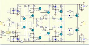
Have the original schema as a base, I reposted here, that is the mother of all variants.
Since you (plural YOU) have the knowledge of simming, there are a lot of "core" aspects you could investigate on this original. One of them is about the heavy (for the signal) L-pad R7/R5 (R8/R6). But we are now dealing with the way to drive the final stage across the diode. So let's point our focus on this first goal: presence/absence of the diode and varying the resistor value.
Would you?
But let's forget about heavy mods like mine, too many variables and understanding each other would be difficult. Let's also forget about accessories like midpoint keepers and so on. We will find a solution for everything at the right time.
If you like, let's go to the core and keep it simple.
Have the original schema as a base, I reposted here, that is the mother of all variants.
Since you (plural YOU) have the knowledge of simming, there are a lot of "core" aspects you could investigate on this original. One of them is about the heavy (for the signal) L-pad R7/R5 (R8/R6). But we are now dealing with the way to drive the final stage across the diode. So let's point our focus on this first goal: presence/absence of the diode and varying the resistor value.
Would you?
Attachments
Last edited:
There is no easy way to automate this in LTspice, so each instance has to be run separately and cannot be displayed graphically.
The base resistor value and the bias current are shown on top. 20W/4ohms
1ohm, 724mA
no diodes 0.09637%
diodes 0.09637%
10ohm, 387mA
no diodes 0.2534%
diodes 0.26338%
20ohm, 268mA
no diodes 0.3891%
diodes 0.3451%
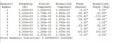
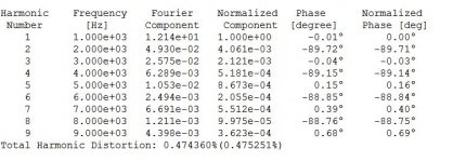
27ohm, 224mA
no diodes 0.474%
diodes 0.3%
30ohm, 210mA
no diodes 0.5092%
diodes 0.3798%
It looks quite fascinating. 27ohm seems to be a sweet spot where the diodes become really helpful.
Selfy is also right: at lower resistor values/higher currents the diodes appear detrimental to distortion.
Could this be a distortion compensation mechanism where use is made of the diode non linearity?
In a real amp the optimal value is perhaps different and may be worth the effort to adjust.
The base resistor value and the bias current are shown on top. 20W/4ohms
1ohm, 724mA
no diodes 0.09637%
diodes 0.09637%
10ohm, 387mA
no diodes 0.2534%
diodes 0.26338%
20ohm, 268mA
no diodes 0.3891%
diodes 0.3451%
27ohm, 224mA
no diodes 0.474%
diodes 0.3%
30ohm, 210mA
no diodes 0.5092%
diodes 0.3798%
It looks quite fascinating. 27ohm seems to be a sweet spot where the diodes become really helpful.
Selfy is also right: at lower resistor values/higher currents the diodes appear detrimental to distortion.
Could this be a distortion compensation mechanism where use is made of the diode non linearity?
In a real amp the optimal value is perhaps different and may be worth the effort to adjust.
20W/4Ohm___I=2240mA___TR hfe avg=90
IF ABSENCE OF DIODE
Idle mA___R mA___R Ohm____R mV
____724___32.9_______1____32.9 too far from diode threshold, diode remains off;
____387___29.2______10___291.9 far from diode threshold, diode remains off;
____268___27.9______20___557.3 close to diode threshold, diode would start switching sometimes;
____224___27.4______27___739.2 close to diode threshold, diode would switch;
____210___27.2______30___816.7 over diode threshold, diode would switch hardly.
At different output power/impedance everything changes.
I have to think about the meaning of all this.
It was hard to align the text!
And here is Damir's circuit as a possible replacement for the diamond.
Would you like to simulate Damir's ciruit with Q10's collector moved to B- and Q12's collector moved to B+?
Would you like to simulate Damir's ciruit with Q10's collector moved to B- and Q12's collector moved to B+?
Collectors moved to rails gives little slower circuit (inpit bkts are not bootstraped). With collectors on emitters, like in schematic you could use lower power, higher ft bjts...
20W/4Ohm___I=2240mA___TR hfe avg=90
My calculation was wrong, I should have considered the peak current at 20Wrms while I considered the rms value. Done again, here the results.
20W/4Ω 2240mArms 3158mApeak
TRhfe 90
IR=(Ipeak+Iidle)/TRhfe
WITHOUT DIODE
Idle mA___IR mA___R Ω____R mV
____724____43.1_____1____43.1
____387____39.4____10___393.9
____268____38.1____20___761.3
____224____37.6____27__1014.6
____210____37.4____30__1122.7
However, if it is a right and licit observation, I do not know where it heads to. I couldn't find any other useful way to elaborate Analog_sa's data.
You should learn to work with some simulator, LTspice is a mess imo, but MicroCap is user friendly and easy to learn.
Brw what's the point of this in the clone thread it's already cloned? 🙂
Is this considered a strictly clone thread? If so, how about we start another thread for dz improvements and tweaks?
Brw what's the point of this in the clone thread it's already cloned? 🙂
Knowledge of sorts. We may start adding diodes all over the place 🙂
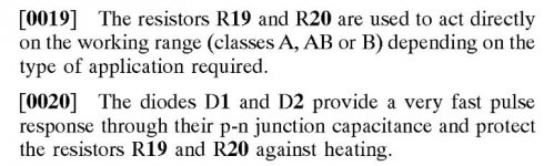
Fwiw, the patent mentions nothing about the diodes forward behaviour apart from protection.
Attachments
Knowledge of sorts. We may start adding diodes all over the place 🙂
Fwiw, the patent mentions nothing about the diodes forward behaviour apart from protection.
Haha patent 😀
I've made power diamond buffer triple 6 years ago with 3 output pairs that worked in open loop and still have the boards collecting dust.. It sounded good with no noticable distortion and it was abused at several parties in open space with load <4 ohms with no problem. Then turned to hi eff speakers and small amps for home use and forgot about it until I've seen this thread...
Attachments
You should learn to work with some simulator, LTspice is a mess imo, but MicroCap is user friendly and easy to learn.
Brw what's the point of this in the clone thread it's already cloned? 🙂
Exams never end (Eduardo de Filippo). Ok, I'll do.
I'm over the age, refusing to learn English, my English allows me to not die hungry. I don't know what "my MicroCap" will allow me but it is worth to try.
Thank you.
I tried LTspice a lot of time ago and renounced.
I installed MicroCap a few minutes ago, the first difficulty was to mirror the transistor symbol, I succeeded in too much time, to be honest.
Will see.
Last edited:
Exams never end (Eduardo de Filippo). Ok, I'll do.
I'm over the age, refusing to learn English, my English allows me to not die hungry. I don't know what "my MicroCap" will allow me but it is worth to try.
Thank you.
I tried LTspice a lot of time ago and renounced.
I installed MicroCap a few minutes ago, the first difficulty was to mirror the transistor symbol, I succeeded in too much time, to be honest.
Will see.
I`ll send you later MicroCap file with all setting so you could play with it and learn faster 😉
Would you like to simulate Damir's ciruit with Q10's collector moved to B- and Q12's collector moved to B+?
Тhere is no change in distortion if that is what you are asking.
Тhere is no change in distortion if that is what you are asking.
So where is the trick? The updated CCS? The added final stage?
Here you go , all is set, you could run Transient, AC, Harmonic Analysis, just change amplitude (power) levels you want, frequency etc ...
Thank you very much!
Later on I will put myself at work.
- Home
- Amplifiers
- Solid State
- Dartzeel amp schematic - build this?