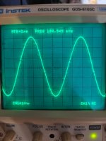
Every scope picture should contain the information about frequency and amplitude settings and the load should be specified.
I notice a contradiction in post 2374 "Amplitude 10 volts" compared to the photo.
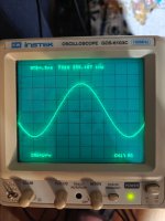
It is hard to decide the blurry pictures hint at an additional problem or its is only the deviaton in crossover range.
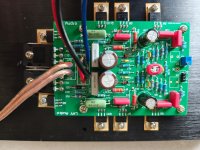
Apart from that we can not know which schematic you used and it is modified or not.
In a circuit like in post 7 bias is dependent on the choice/type of Q9..Q12 and the CCS setting in Q90, Q100.
If you test with very high frequencies and high amplitude it is possible to destroy the output.
I notice a contradiction in post 2374 "Amplitude 10 volts" compared to the photo.
It is hard to decide the blurry pictures hint at an additional problem or its is only the deviaton in crossover range.
Apart from that we can not know which schematic you used and it is modified or not.
In a circuit like in post 7 bias is dependent on the choice/type of Q9..Q12 and the CCS setting in Q90, Q100.
If you test with very high frequencies and high amplitude it is possible to destroy the output.
10 volts in the cell, frequency at the top of the picture, load 4 ohms.Every scope picture should contain the information about frequency and amplitude settings and the load should be specified
The circuit is not changed.n a circuit like in post 7 bias is dependent on the choice/type of Q9..Q12 and the CCS setting in Q90, Q100.
Distortions occur in the voltage amplifier.
Current Q7-Q8 is about 52 mA
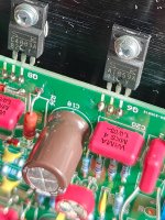
The board is from Ali Express, the transistors have been checked (other ones, not from the set, have been installed).
Attachments
This is how the phone takes pictures. In fact, the picture is clear.It is hard to decide the blurry pictures hint at an additional problem or its is only the deviaton in crossover range.
Do you refer to the schematic in post 7 ?
Current in Q7, Q8 has no influence on output bias.
"10 volts in the cell" what does this mean ?
"Distortions occur in the voltage amplifier" so how can we know where you got your scope pictures ? The output stage has no feedback, but the voltage amplifier has.
Current in Q7, Q8 has no influence on output bias.
"10 volts in the cell" what does this mean ?
"Distortions occur in the voltage amplifier" so how can we know where you got your scope pictures ? The output stage has no feedback, but the voltage amplifier has.
Wrote in post #2,372так как мы можем узнать, откуда вы взяли снимки вашего осциллографа?
When I have time, I'll try to change the correction.It is hard to believe the voltage amp has this form of distortion.

Yes, I checked EVERY part.Вы уверены, что ваша печатная плата Ali и используемые вами детали соответствуют посту 7?
В противном случае мы будем ходить по кругу.
And I'm trying to find transistors. 15032 is about 110, 15033 is about 140, you can't say more precisely.
I have about 50 pieces of 15033 and about 40 pieces of 15032. 🙂
🙂
Last edited:
I think maybe no one has ever done it.Others should try to replicate your tests. Not sure how popular this topic is.
- Home
- Amplifiers
- Solid State
- Dartzeel amp schematic - build this?