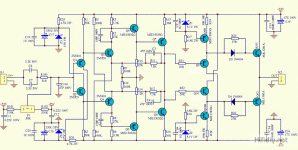
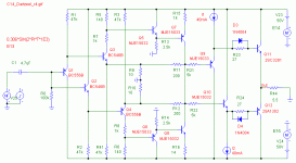
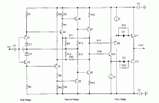
Schematics are available on the net, and this amp has even been simulated by some. Have a look at the company s pdfs, there is a conceptual schematic on the NHB 108 model, you could reverse engineer from there the working currents and voltages. Its a simple design with awful measurements but it has won some awards for its sound.
Mystic it sure is. Build it and come tell us how it sounds.
Mystic it sure is. Build it and come tell us how it sounds.
http://www.dartzeel.com/Pages_F/NHB108_1.html
http://www.dartzeel.com/PDF_Files/AudioManuFR.pdf
http://jipihorn.free.fr/Brevets/WO03043185-FR.pdf
http://perso.wanadoo.fr/francis.audio2/C14_Dartzeel_r4.gif
Performances in simulation (second amp):
http://perso.wanadoo.fr/francis.audio2/Concours_Conception_Ampli_part2.doc
http://www.dartzeel.com/PDF_Files/AudioManuFR.pdf
http://jipihorn.free.fr/Brevets/WO03043185-FR.pdf
http://perso.wanadoo.fr/francis.audio2/C14_Dartzeel_r4.gif
Performances in simulation (second amp):
http://perso.wanadoo.fr/francis.audio2/Concours_Conception_Ampli_part2.doc
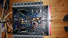
I built one from the cheaper kit on ebay.
PCB was pretty awful, mirrored markings and some markings missing entirely.
Some components were also missing et.c.
Well, I replaced all caps with better ones anyway.
Sound is good. Depth comes close to a good class-A one.
And with my, far too tiny, transformer I get 2x70W @ 7ohm 🙂
This proto looks like crap, because I did not find one suitable transformer and had to use 3. Also this case had a preamp built in so I had to power that one too.
I should try bypassing it.
The problem I have is hum on one channel, I have swapped inputs to make sure it is not the input circuit.
I've had no problems with oscillation, but frequency response of this one only extends to 450kHz -3dB (not 1MHz as manufacturer states)
As this kit has a speaker relay it cannot go up in smoke due to a speaker wire coming loose 🙂
Maybe I did not get an exact copy of NHB-108, bandwidth would suggest that too 🙁
Attachments
Thanks for the schematic!
This is what I bought by the way:
Assembled No Feedback Amplifier Board Base on Dartzeel Amp 2 Board L157 13 | eBay
This is what I bought by the way:
Assembled No Feedback Amplifier Board Base on Dartzeel Amp 2 Board L157 13 | eBay
Found the source of the hum.
Left speaker ground was not connected exactly to the midpoint.
Did a quick fix and now hum is gone, but there is a high pitch 100Hz modulated noise.
My friend pointed out it could be rectifier noise.
I think I will rip out all the Calaf parts from the case and make some high end fast diode rectifiers and use a separate soft start board.
This will save space.
I also removed the input selector and attenuator power supply.
Better keep a power amp as a power amp and not make it an integrated amp at this point.
I'll try to get a separate power supply for each channel too.
I must say the sound is impressive.
I just wish it was softer and warmer.
Detail, depth and power are definitely there.
Input coupling cap is ERO 4uF MKC.
In my experience a 10uF MKL does sound nicer sometimes. (or then it is just my imagination)
Better test this when I have time 🙂
... but there is a high pitch 100Hz modulated noise...
My friend pointed out it could be rectifier noise.
I think I will rip out all the Calaf parts from the case and make some high end fast diode rectifiers and use a separate soft start board...
please look at this file, Dartzell in general has weak pssr (-44dB)
http://perso.wanadoo.fr/francis.audio2/concours_schema.xls
Member
Joined 2009
Paid Member
Hugh Dean is familiar with this type of OPS (he uses something a bit more sophisticated though, I beleive it partly eliminates Vbe drop errors), some wisdom from his direction would be most welcome. I don't think he has found the Cap multiplier to be a good solution and I'm not sure he's ever regulated the power rails to any of his amps - I could be wrong.
I don't think he has found the Cap multiplier to be a good solution and I'm not sure he's ever regulated the power rails to any of his amps - I could be wrong.
Gareth,
Indeed, I have not used regulation in a commercial product. I have tried it in protos, and found generally that it reduces THD, gives very low hum, delivers low impedance but the complexity has a disadvantage - cost, parts count, and reduction of asymmetrical distortion, which adds 'engagement'. An exception is a shunt tube power supply, which sounds wonderful. A ZFB amp does need very careful earthing and lots of filtering; I don't use cap multipliers because I have found they confer the transfer function of the series pass device. I have found a CMC useful, and a CRC filter with 0.15R series resistors.
I had a good look at the Dartzeel 'copy' of the NHB108 and thought it similar to the original conceptual I'd seen in 2005. Generally I try to avoid symmetrical circuits, preferring single ended topologies.
Hugh
Attachments
Last edited:
Wow , how basic. the PSRR would be horrible on this design.
Dual mono maybe. Run the first diamond with a shunt reg. or cap multiply
the whole thing ???
OS
Dual mono maybe. Run the first diamond with a shunt reg. or cap multiply
the whole thing ???
OS
Hugh Dean is familiar with this type of OPS (he uses something a bit more sophisticated though, I beleive it partly eliminates Vbe drop errors), some wisdom from his direction would be most welcome. I don't think he has found the Cap multiplier to be a good solution and I'm not sure he's ever regulated the power rails to any of his amps - I could be wrong.
The OPS would thermally negate if the CCS's were 0 Tc. Cordell's diamond
EF3 example works in a similar fashion.The dartzeel is just the driver/OP ,
(without the predrivers).
Dartzeel's OPS diamond might of been good with 1970 silicon. A 21'st century
EF2/EF3 is "smokin' " fast . My similar input stage can push @ 500V/us ... easy.
PS - this basic design was the starting point for my "kypton-ND" , BTW.
OS
please look at this file, Dartzell in general has weak pssr (-44dB)
http://perso.wanadoo.fr/francis.audio2/concours_schema.xls
-44db is also the distorsion level or so...
Anyway a "design" to be discarded unless one is hassle thirsty..
What is the best way of decreasing the bias a little to suit heatsinking requirements? I have the version of the amp with two output pairs of the circuit shown in post 7, this is what I have bought:
A Pair DC 35V 55V 470uF 100V 200W 200W Superpower Amplifier Board vs Dartzeel | eBay
A Pair DC 35V 55V 470uF 100V 200W 200W Superpower Amplifier Board vs Dartzeel | eBay
What is the best way of decreasing the bias a little to suit heatsinking requirements? I have the version of the amp with two output pairs of the circuit shown in post 7, this is what I have bought:
A Pair DC 35V 55V 470uF 100V 200W 200W Superpower Amplifier Board vs Dartzeel | eBay
Here is a similar looking chassis:
Aluminum Chassis Design for Swiss Dartzeel Amplifier Enclosure HiFi Case DIY Box | eBay
Those 5k base resistors to the first op driver stage are way too high, you will have massive current flowing through the outputs!. Scale these down to decrease the bias of the output stage.
Cap multiplier are great to isolate an input stage from a class a/b output stage unless you can afford the space for huge capacitors in an rc network to isolate the input stage. This Dartzeel schematic as is has many wrong values, wrong details on the input, amongst others since it's just a guess on the actual DZ based off of the simplified schematic.
Colin
Last edited:
- Home
- Amplifiers
- Solid State
- Dartzeel amp schematic - build this?


