In picture 3, transistors -15032 - hFE 130,131 participated
15033 - hFE 180.181
1302 - hFE 115
3281 - hFE 99
small - hFE 214
15033 - hFE 180.181
1302 - hFE 115
3281 - hFE 99
small - hFE 214
This is in the second picture MJE15032
6 pcs. - hFE 108
1 PC. - hFE 111
1 PC. - hFE 98
MJE15033
6 pcs. - hFE 208
1 PC. - hFE 219
1 PC. - hFE 80
6 pcs. - hFE 108
1 PC. - hFE 111
1 PC. - hFE 98
MJE15033
6 pcs. - hFE 208
1 PC. - hFE 219
1 PC. - hFE 80
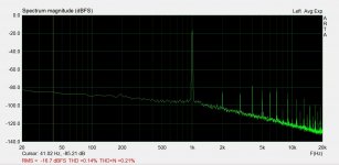
I think the Russian guys from the forum will not mind if I post pictures for you. They show a graph of the original and the blue board of one of the participants, a photo of which I threw off earlier. This is for those who understand.😉
Dear Paroxod, dear Bogdan,Well, that is very good, it looks exactly same, so cloning is successful, great job!
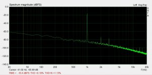
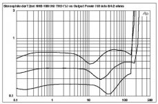
That's lot of distortion but it's 55W. I've seen here high distortion measured at 1W if I remember correctly?
Thank you very much for this extremely useful information - you have brought this conversation to a higher, scientific level. I do appreciate that.
What I can understand from the published graphs is:
1. THD is rather high for both the original and the clone NHB-108
2. Even more troubling is the presence of considerable amount of odd harmonics in the frequency domain.
Could you please post a link to that Russian forum - with a little help from Google Translate I would like to learn more about this essential subject.
Now, with this valuable data there is no need for further "audiophile" talk. Facts are in front of us.
By the way, last week I received my new Rigol 1074Z-S plus. I also consider purchasing a license of ARTA software to be able to perform frequency analysis which is far beyond the capabilities of my oscilloscope. From pure listening there is virtually impossible to make a reliable analysis of equipment.
SARCASTIC MODE ON
Only genuine "audiophiles" are capable of educated listening, we the ordinary mortals must rely on instruments.
SARCASTIC MODE OFF
Thanks guys, it was pleasure hearing from you. 🙂😎
True that, marigno! My Dart is not a 100% clone either. I was just trying to understand what was your idea behind your clone-stein 😎Any of us has its own best project.
Speaking about high-grade parts, here are my ¢5: the parts in the feedback, and at the input of the amp are the ones which make the most impact on the sound. On the original schematic (e.g. post #7): R9/11 + R10/12, and R100. I also think it would be a good idea to invest in high quality resistors for R1/2, say Takman REYs.
I am not so sure how important are the emitter degeneration resistors of the power transistors (if you have more than one output pair). Probably analog_sa can share his observations?
Which Technics schematics do you have in mind?Always been curious if the Technics circuit does more harm than good. The Technics amps used to sound horrible at the time.
* * * * * * *
And one more question to those who have built a "true" clone. Have you ever tried to get rid of the "patent pending" diodes in the bases of the output transistors? To me they do not make much sense. Even in simulation the results without the diodes are prettier.
Which Technics schematics do you have in mind?
Just the non-switching class B principle Marigno uses. Didn't Technics do something very similar?
Well, that is very good, it looks exactly same, so cloning is successful, great job!
That's lot of distortion but it's 55W. I've seen here high distortion measured at 1W if I remember correctly?
1W and 50W dist into 7.4ohms
Attachments
This seems to go quite in depth, yet one of the most obvious PS improvements: synchronous rectification, has not been implemented.
Well, this Russian branch is strictly for cloning and assembling the original 108 of the first version, any deviations are punished. If you know what I mean.😀😉
Hahaha. I bet the original sound better, at least 17K$ better... ��
Great job guys.
Great job guys.
Штрафной батальон?* 😱Well, this Russian branch is strictly for cloning and assembling the original 108 of the first version, any deviations are punished. If you know what I mean.😀😉
*) Strafbatallion
Last edited:
Well, not so strictly, of course, but deviations from the topic are not welcome, they are chopped up.🙁 Here it is simpler.🙂 This is of course all jokes, you need a little and will be dispelled.😉😀
Anyone tried to include output stage in the feedback loop to hear how it sounds?
Too old and prejudiced for such a test 🙂
And it may need a Boucheron at output once the loop gets closed. And an inductor.
But the circuit started life like that, right? And no one ever thought that old Revox was so great. The Chinese never cloned it either 😎
I will also be repetitive, but if one wants to remake the 108 the Chinese card is an excellent approach, you buy it, it sticks and it also plays according to the chosen filter cell;
if you want to exaggerate, you can select the assets which, being an open loop, is a mandatory operation if you don't trust the Chinese.
Well.
Wanting to review the Chinese scheme, which is then identical to the original, I would consider:
- the painful input power supply which, with those zener, appears to be an announced contradiction and a sure source of noise in such a critical scheme
- the input capacitor which, at least, I consider a real calamity, as a capacitor quality
- then I would consider the bypass, if needed, of the supercap: I would try mica parallel to polypropylene, both as a composite bypass of the supercap which is a real sonic nonsense
- I would eliminate the 4 ceramic capacitors in the diagram by replacing them with equivalents in mica or polystyrene, to be tested, but I eliminate the ceramics
- then you can think of SMD chips with PNP and NPN matched for input.
.............
but
........
so it is no longer a 108, but it could sound better while retaining its DNA derived from the open ring which, in 108, it seems to have taken to limit it
....
Last edited:
- I would eliminate the 4 ceramic capacitors in the diagram
Never had ceramics there, even for comparison. WIMA FKP from my first clone.
The supercaps are an unnecessary compromise, just don't add them.
The DNA of this amp is mostly in the voltage gain circuit. The output diamond generates excessive and ugly distortion, well above what an output follower should generate. It is the one area really worth improving. As much as i like the sound at lower power it changes perceptibly once the output exceeds a couple of watts. Improving the diamond a little can bring the distortion down several fold. Damir has published such an improved diamond, which, at least in simulation behaves much better than the original 108 output.
in my Chinese PCB, because of this I speak, there are 4 ceramics, that's why I SUGGEST to eliminate them, then one does as he prefers.
The supercap is used to cancel the offset which, otherwise it is difficult to control, but the supercap is a sonic disaster, that's why I RECOMMEND to try the bypasses.
Then if one replaces the 4 5551 and 5401 inputs with the chip containing PNE and NPN, the offset is controlled fine.
The supercap is used to cancel the offset which, otherwise it is difficult to control, but the supercap is a sonic disaster, that's why I RECOMMEND to try the bypasses.
Then if one replaces the 4 5551 and 5401 inputs with the chip containing PNE and NPN, the offset is controlled fine.
- Home
- Amplifiers
- Solid State
- Dartzeel amp schematic - build this?