I avoid these with the same fervor i avoid ceramic caps.
Soundwise, and perhaps in measurable distortion, nothing is safer than metal films. Now and then you get resistors using other tech like the tantalum, carbon film or wire that have appealing sonic flavours but i feel their sonic signatures are more apparent than good metal films.
Which are good metal films to use?
well, ... Except pretty women. 😚... Everything in the world is Chinese.😀
Thank you very much to all of you!
I am more familiar with designs than components so, with your help, I was able to assemble the following listing:
0.5W resistor - PRP PR9372 metal film, $0.45 on partsconnexion.com;
2W resistors - TKD CM2 metal film, $1.95 on partsconnexion.com;
10W resistors - Ohmite wirewound, $2.22 on Mouser.com;
2N5551/5401 - MMDT5451-7-F NPN/PNP array, $0.38 on Mouser.
Today the Ali tracking about my PCBs package is totally unclear. So I will not place yet an order for components.
It's fairly large thread and I don't get it what is happening..? There's a clone based on schematic and it's close in measurements to original or not? Optimizing the circuit to measure better wouldn't be hard but that's not a clone then... So what is the goal of the thread?
What do you need the 10W resistors for?
I believe he has altered the Dartz architecture a bit in order to accommodate a Technics new class A output variant. As a consequence the ex-Dartz output transistors now work into 5k loads which at high output get a bit toasty.
Not sure how happy would Revox be with all this 😀
There's a clone based on schematic and it's close in measurements to original or not?
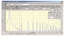
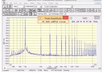
Yes, the measurements are pretty close.
And you are quite correct 🙂
But there is a 108 Model 2. And lot's of other models too.
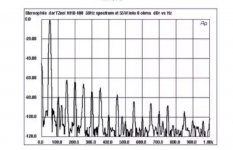
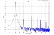
I think the Russian guys from the forum will not mind if I post pictures for you. They show a graph of the original and the blue board of one of the participants, a photo of which I threw off earlier. This is for those who understand.😉
Attachments
What do you need the 10W resistors for?
Look at #1498 Rb4 and Rb5.
In this case, why don't you go for Mills or Mundorf wire wounds?
Speaking of #1498, I wonder what is the purpose of Q11/12 to be run at 45mA and Q13/14 -- at 15mA... not to mention the myriad of output transistors, all sharing just 50mA at idle?
PS: If you need that many output transistors, why not consider the original Revox schematic, with a feedback only "around" VAS?
Last edited:
PS: If you need that many output transistors, why not consider the original Revox schematic, with a feedback only "around" VAS?
I asked myself the same question and came to the conclusion he already had the clone amp and didn't want to do much mods to it. Yes, the original outputs are now pointless, but working in class A with that load they wouldn't do much damage, right?
It's a long sequence of strange decisions but if it works, great 🙂
Always been curious if the Technics circuit does more harm than good. The Technics amps used to sound horrible at the time.
I guess I was able to answer bogdan_borko. This is another clone.🙄
Borko knows the answer well. His was just a rhetorical question.
about MJE15032/33
both left (AFM date code) are genuine ON , NOT the third one :
- pins are flat, not curved
- mounting pad is not rectangular , but with 2 inserting "holes"
Don't forget that strictly complementary pair MUST sort same Hfe
😉
from left to right: mouser - 108 board - eBay
both left (AFM date code) are genuine ON , NOT the third one :
- pins are flat, not curved
- mounting pad is not rectangular , but with 2 inserting "holes"
Don't forget that strictly complementary pair MUST sort same Hfe
😉
Last edited:
I guess I was able to answer bogdan_borko. This is another clone.🙄
Well, that is very good, it looks exactly same, so cloning is successful, great job!
That's lot of distortion but it's 55W. I've seen here high distortion measured at 1W if I remember correctly?
In this case, why don't you go for Mills or Mundorf wire wounds?
Speaking of #1498, I wonder what is the purpose of Q11/12 to be run at 45mA and Q13/14 -- at 15mA... not to mention the myriad of output transistors, all sharing just 50mA at idle?
PS: If you need that many output transistors, why not consider the original Revox schematic, with a feedback only "around" VAS?
Any of us has its own best project. My plans are different from your kind suggestion and cannot consider the Revox design.
The WHA-217 is an exercise made on the NHB-108 base (because a PCB is available) with the precise purpose to test the NSCB stage, which needs to work without any feedback, without involving too many resources. Considered its good sound, far over expectations, I want to invest some more money and time to have it finalized to work at its best, by rebuilding it with top quality components. It is a closed project/experiment that only needs to be pushed at its best.
50mA of the NSCB stage is a round-up value, I want it to be as low as possible, the transistors must work in B-class. But, having no instrumentation, I had to set it by my ears.
46mA on diamond drivers are a reduction of 118mA original value that is too much in heat and a waste in driving capability. Even 46mA is a lot, however, a bottomless reserve to drive the NSCB stage having another transistor in the middle (about 4600mA as a result). 15mA on diamond final transistors is the result of choosing a 4.7KOhm resistor as a load, it does not need to be higher.
My ideal project has two principal fixed points: the open-loop bandwidth must be at least double than the audio band, and no loop must exist as feedback in the audio band across any stages/functions. Secondary goals are achieving about 40Vrms output voltage with a strong current and avoid an A-class output stage.
Actually my next plan is to use an Aikido as front-end/VAS and a back-end composed by a diamond buffer followed by an NSCB stage. Servo circuitry to keep the midpoint, to stabilize the idle point, to limit inrush current, to protect speakers are still to be designed.
My dream project is to have 40Vrms with the sound of a 300B SE, using precisely a 300B and a feedforward approach for the output SS stage without using any feedback in the audio band. This will remain a dream, I do know it for sure, I have to write it down, buy a couple of 300B, their sockets, and hide everything in a secret place, good for the next life.
I love the good OTL sound, one the best I have ever listen to, but I will not approach any OTL design because of its incredible consumption of energy and uncomfortable heat.
I will check for Mills and Mundorf. thank you.
Last edited:
about MJE15032/33
both left (AFM date code) are genuine ON , NOT the third one :
- pins are flat, not curved
- mounting pad is not rectangular , but with 2 inserting "holes"
Don't forget that strictly complementary pair MUST sort same Hfe
😉
Are you sure about the second transistor? It seems to be exactly the same of the first that is the good original one. Can I trust on it? I have some of them from burnt boards.
The hfe between PNP/NPN is a problem, you have to use what you get. Mouser and Digi-Key do not match them. And I don't trust anymore buying transistors elsewhere than official vendors. Unless you have a good source to suggest. I will buy some more and try to match them with the ones I have, including the "second type" in the picture.
- Home
- Amplifiers
- Solid State
- Dartzeel amp schematic - build this?