MicroCap is absolutely fascinating, a new world for me.
I would not have entered this world if I had not been in this forum.
Too soon to say the findings, they could be highly incorrect.
Very glad to you!
I would not have entered this world if I had not been in this forum.
Too soon to say the findings, they could be highly incorrect.
Very glad to you!
MicroCap is absolutely fascinating, a new world for me.
I would not have entered this world if I had not been in this forum.
Too soon to say the findings, they could be highly incorrect.
Very glad to you!
Cheers 🙂
I worked with MicroCap taking advantage of some free time. I am not yet able to see the Fourier graphics but, looking at the default graphic about harmonic distortion, I can well understand that the total harmonic distortion in my WHA-217 is high. Not only this, the odd harmonics are higher than the even ones, that is normal in a push-pull output stage; we can expect to see the good monotonically decreasing distortion only in single-ended architectures.
I will never build any main amplifier in the single-ended way, not made out of tubes, nor transistor and only in B-class. And will never use any feedback loop from the output operating in audio bandwidth. So I have to cohabit with the ugly form of distortion.
The good is that, despite the bad distortion form, the sound is really good! The guy that had a fancy HiFi shop in Salt Lake City came to hear my WHA-217 and was impressed. Everybody that enters my house is impressed by the sound. Finally, I also have to say that I really like this sound and not because it comes from my work, I always manage to be objective and, indeed, I am much more critical about what I built myself. I also have a group of audiophile friends in Italy, we educated ourselves to the good sound listening to music and going to see (and listen) all HiFi galas in Rome every year. Not always, but sometimes there is something good. So I can judge myself able enough to understand the quality of a HiFi chain.
I never had the pleasure to listen to the original nor the clone of the NHB-108, but I can understand that it could be not suitable for all kinds of speakers for the fact it is heavily limited by the CCSs. Perhaps, removing this limit adding one more stage (Damir's, mine), very powerful, lowers the distortion and increases the ability to drive more speakers (MicroCap says too).
I received today the PCBs, I'm going to order the best components I selected thanks to the recommendations of many of you; I will also try to operate the mod about Baxandall super couple. I will let the forum know about the results but, I think, not before the middle of October.
Last edited:
..... we can expect to see the good monotonically decreasing distortion only in single-ended architectures.
Well, that is not true.. What is WHA-217?
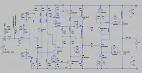
Adding one more stage to the NHB-108 is easy for any experimenter with a passion for electronics, try a stage like mine with only two output pairs, you don't have to change too much on the original PCB (Damir's solution is a bit more complicated). It is worth it. Referring to WHA-217 schematics: forget about NSCB (resistors and diodes on output pairs bases and remove one diode from the bias adjustment). Do not pay attention to my mod on CCS, leave it original. Fire up with a variac, one eye to the voltmeter, the other eye to the amperemeter (on one emitter resistor), adjust the bias to the very possible minimum by inserting resistors (0.22 to 2.2Ohms should fit) in serie with the remaining diode and stop when cross over distortion is no more audible. Then try those speakers that never paired well with the original schematic.
I didn't follow the suggestion by Domenico about integrated CCS because I couldn't find any suitable components. But yesterday, while browsing on Mouser, I found the IXCP10M45S (TO220 - 450V/100mA max), frequently used as a plate load. I will try this one too.
All push-pull stages have the even harmonics almost canceled because it is an unavoidable feature of the circuitry. Things are a little different with a very heavy bias, over than A-class. A truly expensive good sounding stove.
Last minute edit: PCBs from Ali, the green ones, are very good quality ones.
Last edited:
I found the IXCP10M45S (TO220 - 450V/100mA max), frequently used as a plate load. I will try this one too.
Somewhere along this monstrous thread i mentioned replacing the CCS with a depletion mosfet. It definitely brought some modest improvement.
The 10M45S is not very good sounding imho and nor is the Dn2540. At the moment one of my Dartzeels plays with my favourite IXTP01N100D but i see no reason the cheaper T0-251 part won't work just as well.
I'm just watching the tread, not interested in making this thing, I made few variants of output power diamond buffer long time ago.Adding one more stage to the NHB-108 is easy for any experimenter with a passion for electronics, try a stage like mine with only two output pairs, you don't have to change too much on the original PCB (Damir's solution is a bit more complicated). It is worth it. Referring to WHA-217 schematics: forget about NSCB (resistors and diodes on output pairs bases and remove one diode from the bias adjustment). Do not pay attention to my mod on CCS, leave it original. Fire up with a variac, one eye to the voltmeter, the other eye to the amperemeter (on one emitter resistor), adjust the bias to the very possible minimum by inserting resistors (0.22 to 2.2Ohms should fit) in serie with the remaining diode and stop when cross over distortion is no more audible. Then try those speakers that never paired well with the original schematic.
I didn't follow the suggestion by Domenico about integrated CCS because I couldn't find any suitable components. But yesterday, while browsing on Mouser, I found the IXCP10M45S (TO220 - 450V/100mA max), frequently used as a plate load. I will try this one too.
All push-pull stages have the even harmonics almost canceled because it is an unavoidable feature of the circuitry. Things are a little different with a very heavy bias, over than A-class. A truly expensive good sounding stove.
Last minute edit: PCBs from Ali, the green ones, are very good quality ones.
What's the bias current per pair in that 11pair thing? I guess it sounds better then original cos it's working in class A for the first 5-10W.
It is biased as B-class as possible, the bias is a bit more over the audible cross-over distortion, I think less than 50mA total for all couples.
Somewhere along this monstrous thread i mentioned replacing the CCS with a depletion mosfet. It definitely brought some modest improvement.
The 10M45S is not very good sounding imho and nor is the Dn2540. At the moment one of my Dartzeels plays with my favourite IXTP01N100D but i see no reason the cheaper T0-251 part won't work just as well.
I saw your post at around #700. But no schema.
i'm I correct if I say, about the positive rail, drain (of the depletion mosfet) to +B, gate to the user, and source to the user (with gate) through a resistor (value)?
My goal is to obtain the lightest possible load for the VAS.
my favourite IXTP01N100D...
I searched on the net and could validate my idea about the resistor placed at the source.
I compared on Mouser different MOSFETs and found out that the IXTP01N100D performs as the best, among 11, in capacitance (the lowest). But performs at a low level in transconductance and shows the highest Rds(on).
Looking at SOA graphic @75C: for my application, it must deliver less than 50mA @140V possible swing, it could be OK even if very close to the left limit imposed by the Rds(on) but, in the original circuit, it must deliver 118mA @100V possible swing, that seems to be over the Rds(on) left limit. Right limit is respected in both cases.
Am I wrong?
Last edited:
Look at the datasheet, that mosfet won't work as ccs at Vds lower then 20-25V (at least). Btw Rds(on) is irrelevant for intended application.
Look at the datasheet, that mosfet won't work as ccs at Vds lower then 20-25V (at least). Btw Rds(on) is irrelevant for intended application.
Absolutely. And the more extra volts, the better.
A bigger Rds on is probably beneficial in this application 🙂
Never drew a circuit, but here it is now, obviously with the wrong model. The source resistor for this current is around 20ohms and due to dissipation should not be a trim pot.
Not sure i prefer the sound because the ccs is better or because there is no zener.
Attachments
Why do I sense such a strong dislike for zener diodes 😀 IMO they perform quite all right sonically, given you do not need high voltage stability.
analog_sa, I thought you were using mosfet css as a dynamic load on the input transistors, now I see you use them in the diamond.
Has anyone bothered to try CSS for the input pair instead of the 56k resistors?
analog_sa, I thought you were using mosfet css as a dynamic load on the input transistors, now I see you use them in the diamond.
Has anyone bothered to try CSS for the input pair instead of the 56k resistors?
Last edited:
mosfet css as a dynamic load on the input transistors, now I see you use them in the diamond.
You are right. My intention was to try them at both spots. I think i got distracted 🙂
Otoh, current sources do not necessarily sound better than resistors at all positions.
And talking of zeners, i agree with Domenico: those at the input must go. Even made a pcb with a 317 only never got around using it.
Now after 3 in the Club my Dartzeel is in use at home. First time at use in both channels and on my best speakers. Must admit that I enjoy the sound when playing some old jazz. Verve Ella and Basie.
Hello Erlend
greetings and nice to know you are enjoying the amplifier is it possible to
share the schematic you have used sucessfully my dartzeel pcbs should be
arriving any day.
warm regards
Andrew
greetings and nice to know you are enjoying the amplifier is it possible to
share the schematic you have used sucessfully my dartzeel pcbs should be
arriving any day.
warm regards
Andrew
- Home
- Amplifiers
- Solid State
- Dartzeel amp schematic - build this?