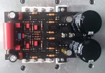
I don't like that the "small" transistors do not touch on the flat side. Also R13/14 are smd. I guess that's the master's way 😀

DARTZEEL
Hello
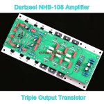
greetings picture of pcb i have ordered looks different to the other
models seems to have some servo feedback to reduce offset
has anyone tried this pcb
warm regards
Andrewhttps://fr.aliexpress.com/i/32819654593.html?spm=a2g0w.12057483.0.0.6be8b20eN3xoJ5
Hello
greetings picture of pcb i have ordered looks different to the other
models seems to have some servo feedback to reduce offset
has anyone tried this pcb
warm regards
Andrewhttps://fr.aliexpress.com/i/32819654593.html?spm=a2g0w.12057483.0.0.6be8b20eN3xoJ5
Attachments
bogdan_borko The author of this project was here as a guest, if you have any questions, I think he will answer.🙂
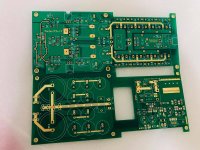
I have the "458" PCB, I was wondering sharing the GERBER.
But some may say it's not 458, and argue about that.
Should I share it?
I've built that, and it's way better and delicate than the 108.
2 AVX supercap were used.
Just want to make some contribution to the DIY community.
The simulation runs well, and the real one runs well too. Actually, I don't care it's 458 or not, it sounds just way better than 108.
Attachments
The simulation runs well, and the real one runs well too.
In what sense does the simulation run well? Insufficient current gain for the output stage overloads the VAS and causes excessive amount of distortion. This can only be cured with output darlingtons.
Will be very interesting if you can prove otherwise. Distortion @1W/4ohms?
In what sense does the simulation run well? Insufficient current gain for the output stage overloads the VAS and causes excessive amount of distortion. This can only be cured with output darlingtons.
Will be very interesting if you can prove otherwise. Distortion @1W/4ohms?
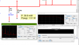
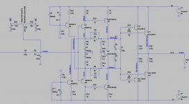
BW: DC to 268KHz -3dB, Gain=28.7dB
THD=0.165% @1KHz 1.5W/4ohm
Attachments
Insufficient current gain for the output stage overloads the VAS and causes excessive amount of distortion. This can only be cured with output darlingtons.
Insufficient bandwidth of driver stage is a usual cause of instability. The design in post #1675 is actually not too bad. There is a slim hope. Q5/Q6 are not needed for anything.
Some time ago I was experimenting with different VAS arrangements for my semi-clone. Initially I was also thinking “Q5/Q6 are not needed for anything”. Later it came to my surprise that adding some extra gain in the VAS open loop was quite beneficial for the amplifier sound. Measured performance of the VAS did not change much...
PS: That is one of the main reasons I was quite skeptical about the alleged schematic of 458. The other being the insufficient drive for the output stage.
PS: That is one of the main reasons I was quite skeptical about the alleged schematic of 458. The other being the insufficient drive for the output stage.
Last edited:
Insufficient bandwidth of driver stage is a usual cause of instability. The design in post #1675 is actually not too bad. There is a slim hope. Q5/Q6 are not needed for anything.
Your post is out of context. We were discussing the 458 circuit.
BW: DC to 268KHz -3dB, Gain=28.7dB
THD=0.165% @1KHz 1.5W/4ohm
Sorry, i assumed we were discussing the 458 circuit published in the Hungarian forum by Shany.
Apparently the circuit you built has an added pair of emitter followers which, provided they run at a high enough current will be more capable of driving the outputs.
Please confirm the attached is the correct circuit. What is the current through U2/U8?
At high power your circuit will suffer the same issues as Shany's: insufficient current gain of the outputs. Assuming a current gain of 90, and a peak load current of 10A (200W/4ohms) this means 111mA of base current. Where will it come from?
Attachments

The VAS stage is able to provide more output current than its idle current of course. Do not forget it, these circuits are designed to create lot of distortion ( purposive distortion creating ) which can cause the illusion of exaggerated living and spatial sound ( The original parts decrease this illusion to generate the sweet and precious balance ... )...At high power your circuit will suffer the same issues as Shany's: insufficient current gain of the outputs. Assuming a current gain of 90, and a peak load current of 10A (200W/4ohms) this means 111mA of base current. Where will it come from?
My measurements in practice:
Vout=39,3Veff / 8,2Ohm ( 188W ) / 1kHz - THD=0,085%
Vout=38,8Veff / 4Ohm ( 376W ) / 1kHz - THD=0,11%
Last edited:
Thanks for the input Shany.
A simple test is to measure the distortion at the output of the VAS with or without a load applied at the output. Both in simulation and measurement i find a significant difference, especially at or below 4ohms.
Btw, my reduced output circuit based on yours has a much higher distortion. Do you see a reason for this? I have run the drivers at 100mA as well.
Attachments
My posts are out of context partially due to the rapid paradigm shifts. Suddenly the three voltage followers are gone. Yes, the heavy load constituted by the bipolar output transistors in parallel will plunge the common emitter drivers into a state of permanent high frequency saturation.
- Home
- Amplifiers
- Solid State
- Dartzeel amp schematic - build this?