I also bought the one pair version. No problem with that. The two pair version have a bias problem. It is all to low. Yesterday I saw the two pair version on their site.Which board with two pairs of output devices? All they have now is "finished board" with a single pair. I have purchased bare boards of the same configuration elsewhere and my amplifier works very well indeed. I have used components from reliable source. What went so terribly wrong?
Have you yet tried the Hungarian circuit yourself?
Will start working on the board very soon. What do you think about replacing the CCSs with depletion mosfets?
no NFB on the outputs, (post 623) this can't be speccing out very well with only 100ma total bias class AB.
it would have to be at least 500ma to get 0.2% at a watt or less.
it would have to be at least 500ma to get 0.2% at a watt or less.
analog_sa, CCS with depletion mosfet sounds like a very good idea — neat and low-part approach.
analog_sa, CCS with depletion mosfet sounds like a very good idea — neat and low-part approach.
Yes, certainly. And an adjustment option. The question is whether a better performing ccs would not change the sound character and whether such a change is desirable.
Last edited:
it would have to be at least 500ma to get 0.2% at a watt or less.
Well, it is not a first watt amp 🙂
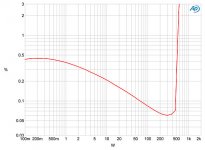
8ohm 1kHz distortion of the original. Lower impedance behaviour is significantly worse. Still, pretty good for PA 😛
Attachments
@analog_sa / @selfy
Once upon a time a group of »smart« companions discussed how many teeth there are in a donkeys mouth. It was so intense debate that one of them even opened the Holly Sctipture to seek the answer.
... instead of going downstairs into the stable, open donkeys mouth and count. That simple is that.
Do you really think that simulation is good enough to assess the schematics? Do I have to explain the difference of simulation and building the real subject under the test.
The man has built that amplifier and it works well.
Really, do you know how many teeth there are in donkeys mouth?
And, by the way, I have quite a bit of experience with simulations, solving sets of nonlinear equations, transients, integration of differential equations, e.t.c. ... and I know wehre limitations are. I also know advantages of real world experiments.
Thanks Erlend 🙂,I also bought the one pair version. No problem with that. The two pair version have a bias problem. It is all to low. Yesterday I saw the two pair version on their site.
This is usefull information. As the matter of fact for the most of us the single pair original device is loud enough to listen to the music under normal room conditions.
I have another pair of normal bare boards and intend to play with them.
Thanks again and have a pleasant day.😎
Berlusconi, you are so killing the diy spirit here, and our constant urge to tweak something 😀 😀 😀
Still I am not quite convinced Shany’s schematic is the real one, especially with the added voltage regulators after the zener diodes. Don’t get me wrong, I like the simplicity in it, I just doubt it is the 458 true schematic 😉
By the way, has anyone built both 108 and 458 and compared them?
Still I am not quite convinced Shany’s schematic is the real one, especially with the added voltage regulators after the zener diodes. Don’t get me wrong, I like the simplicity in it, I just doubt it is the 458 true schematic 😉
By the way, has anyone built both 108 and 458 and compared them?
Dear selfy😎,Berlusconi, you are so killing the diy spirit here.... 😀 😀 😀
I do sincerely apologize because I have made you feel that way. Please note that this is a full sincere apology therefore I use exactly wording »because« instead of these half-apologies with word »if« involved. Also, I do respect your valuable contribution also elsewhere. The same goes to analog_sa. I respect exceptional capabilities of the both of you.
In fact, my intentions were quite opposite: what I mean is that our valuable member shany deserves equal measure of respect for his, obviously in-depth work. Isn't suspicion about the validity of his schematics equally killing diyers spirit. What I really wanted to say is let's respect difference of ideas and give up refusing others out of hand.
From my side shany deserves full credit for his valuable work.
I wish all of you sunny and pleasant May 1st holliday.🙂
Berlusconi, no need for apologies 🙂 I was joking about stopping us to tweak things. In any way, I find this thread quite interesting and now I am waiting for Herve to patent 468 so we can steal the schematic 😎

THIS thread might be helpful.What is most important Vbe or Hfe?
TomWaits has presented some values for MJE15032 and MJE15033. It is interesting to note that MJE15032 are in the range 76-119 and MJE15033 have higher values which are also more uniform, in range: 137-138. Note also that there were no exact matches: all MJE15032 values are lower than the lowest among MJE15033 values.
THIS post could be a good explanation.
And if you go quite a few pages back you may find suggestion by UltimaLegione to keep pairs back-to-back close together with shrinking tube to keep them at the same temperature. This suggestion seems to be well founded because caracteristics are temperature temperature dependent.
Please, keep us informed about the progress of your work. In the next week I am starting work on yet another pair.
Good luck!🙂
Last edited:
Bought around 50 of each.
Taking it way too far imho. These are a part of a high nfb circuit; matched or not distortion is many orders of magnitude below the distortion of the output buffer.
Perhaps matching at the output so each halfwave experiences the same current gain is more worthwhile
As for thermal bonding, i have one amp with and another without. Hardly any difference in offset.
Is there a Gerber file for the Hungarian schematic?
I stumbled across this YouTube video and learnt a new word :
YouTube
Mr D., eat your heart out! This guy designs and builds builds a 2000w amplifier in no time 🙂
Maybe a 478? 🙂
$2 for a small card from Hong Kong + shipping
Is there a BOM for the Hungarian design?
I stumbled across this YouTube video and learnt a new word :
YouTube
Mr D., eat your heart out! This guy designs and builds builds a 2000w amplifier in no time 🙂
Maybe a 478? 🙂
$2 for a small card from Hong Kong + shipping
Is there a BOM for the Hungarian design?
Last edited:
Interesting indeed,Is there a Gerber file for the Hungarian schematic?
I stumbled across this YouTube video...
Maybe a 478? 🙂
$2 for a small card from Hong Kong + shipping
Is there a BOM for the Hungarian design?
For simulations here we use predominantly LTspice.
What we need here is a 100% copy, not just schematic but topology of the original pcb. Some computer program can not design proper layout. Only very skilled people who have opened and studied particular amplifier may successfully perform that task. Expert knowledge is required.
For us, real amateurs there are no shortcuts. We must learn a lot before we even consider building something own, from scratch. At least I have to learn a lot, I am just a newbie but rather enthusiastic.
So all that is needed is an original PCB and an X-ray machine, then?
(to follow traces in a multilayer card)
(to follow traces in a multilayer card)
Last edited:
Dear analog_sa,Taking it way too far imho. These are a part of a high nfb circuit; matched or not distortion is many orders of magnitude below the distortion of the output buffer.
Perhaps matching at the output so each halfwave experiences the same current gain is more worthwhile
As for thermal bonding, i have one amp with and another without. Hardly any difference in offset.
You have just saved me from spending a great deal of time and money (and headaches). I always want to know that I have done everything to do things right. Therefore I also wanted to purchase two piles of 5401/5551 transistors. Now I can simply abandon any thought about matching 5401/5551 transistors and consider just output devices.
By the way, may I ask for your opinion on the following questions:
Q1: is it correct/advantage to replace ceramic 47pF and 150pF capacitors with Wima film capacitors FKP2 47pF 1000V, RM5 and film capacitor FKP2 150 pF 63V RM5?
Q2: is it correct/advantage to replace 330uF/35V with 100V rated capacitor?
Thanks again for all your help and advice.🙂
Last edited:
- Home
- Amplifiers
- Solid State
- Dartzeel amp schematic - build this?